Mars rover vehicle self-senses and moves
Using camera imaging and decision-making software, the Mars rover vehicle constructs 3-D models of the surrounding terrain and then plans and makes safe movements.
By C. G. Masi,Contributing Editor
Imagine that your vehicle's power-steering system is faulty and there is a delay between the time you turn the wheel and the time the front wheels turn. In fact, consider that the front wheels don't turn until a few minutes after you turn the steering wheel. Moreover, imagine that you experience the same delay when you press the accelerator or brake pedal. Even worse, contemplate not being able to see through the windshield that big rock in the road for several minutes.
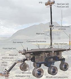
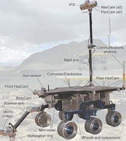
FIGURE 1. The Field Integrated Design and Operations (FIDO) prototype planetary exploration rover vehicle comprises six different vision systems that support its on-board navigation and scientific systems. Four systems, designated NavCam (Navigation Cameras, PanCam (Panoramic Cameras), Front and Rear HazCams (Hazard Cameras), and Sun Sensor, collect the raw imaging data needed to identify hazards in the rover's destination path. The on-board computer stores this information for future reference as well as for immediate use by the path planner.
This is not a picture that the National Transportation Safety Board would approve of, but it's exactly the situation that scientists exploring the surface of Mars confront every time they take their intelligent rover vehicle out for a spin. Consider their problems in controlling, directing, and commanding the rover's terrain movements. The time delay to send a radio-based message from Earth to the rover on Mars varies from just less than three minutes (2.8 minutes to be exact) to just more than 5.5 minutes, depending on where the two planets are in their respective orbits around the Sun. There is an equal time for the return trip; so it takes a minimum of 5.6 minutes to make a command and then see the result.
Say, you start the rover. Then, you wait because you know that the TV monitor will show the rover just sitting there for another 5.6 minutes before it apparently starts to move. Of course, by the time the signal showing the rover starting to move appears on the monitor, the actual rover on Mars will have been driving somewhere ahead for 2.8 minutes. It could have traveled over the horizon from where it started, fallen over a cliff or, more likely, piled up against a rock.
Obviously, these are not viable research situations. Because of the time delays experienced during interplanetary communications, the Mars rover exploratory vehicle must be able to seek, evaluate, and command its own surface movements. As a result, NASA scientists have designed a vision-based intelligent vehicle that self-directs its operations.
Smart puppyThe NASA Jet Propulsion Laboratory (JPL; Pasadena, CA) testbed rover vehicle—Field Integrated Design and Operations, or FIDO—contains several vision-based systems that keep its on-board computer appraised of the terrain around it (see Fig. 1). The FIDO research group supports both current and future robotic missions on the surface of Mars. In particular, it conducts mission-relevant field trials that simulate mission operations scenarios and validates rover technology in the areas of rover navigation and control, instrument placement, remote sensing, scientific telemetry processing, data visualization, and mission operations tools.The group is currently supporting the NASA/JPL Mars Exploration Rover (MER) project that will launch and land two rovers onto the surface of Mars in summer 2003. The rover is being used now to give scientists and operations personnel the chance to simulate and operate a fully instrumented vehicle in challenging geological settings on Earth that are similar to the expected settings on Mars. This setting is currently the Mojave Desert in California.
The FIDO rover is 1 m long, 0.75 m wide, and 0.5 m high. When extended, its mast stands 2.03 m above the ground. The vehicle's mass is 68 kg, and it can travel over the ground at a speed of 6 cm/s. It has a six-wheel rocker-bogie suspension. This suspension, patented by JPL in the mid-1990s, consists of six powered wheels arranged in two sets of three wheels per side. A free pivot connects the bogie, which holds the front and middle wheel, to the rocker arm, which connects the rear wheel to the body. The rocker joints on both sides of the suspension connect to and support the main chassis of the rover through an internal differential mechanism, which ensures that all six wheels remain in contact with the ground at all times. It also allows the rover to safely traverse rocks and square-edged obstacles 30 cm high-more than 1.5 times FIDO's 20-cm wheel diameter.
Blindly moving the robotic arm around in unfamiliar territory might seriously damage the equipment or put it out of action permanently. The problem of navigating a robotic arm is, in many ways, similar to the problem of navigating an autonomous vehicle, and the solution is similar. Stereoscopic cameras feed video images to image-processing and terrain-modeling software that enable the computer to make important command decisions.
Roving eyesThe FIDO rover contains six different vision systems that help control its motions. Four vision systems (navigation cameras, panoramic cameras, hazard-avoidance cameras, and sun sensor) provide information to help the rover plan and execute trips and avoid problem areas. The other two vision systems gather visual information related to the on-board scientific instruments.Most of the vision systems consist of stereo camera pairs that provide 3-D information to the on-board computer. This computer consists of a 266-MHz CPU board, four serial ports, 32 Mbytes of RAM, PCI and ISA bus support, a 100-Mbit/s Ethernet board, monochrome and color 8-bit frame-grabber boards, and assorted analog and digital-signal-processing boards.
The cameras are positioned to obtain slightly different views based on the cameras' relative parallax. These different views help to determine the range to various features in the surrounding scenery.
Navigation cameras.The two navigational cameras are low-spatial-resolution, monochrome, stereo cameras mounted on a 25-cm baseline. They present the rover with a 43° by 32° field of view and a 100-m range for traverse planning. Their images are digitized at a spatial resolution of 640 X 480 rows X 8 bits.
Panoramic cameras. Two false-color, narrow-angle panoramic CCD cameras complement the wide-angle rover navigation cameras, but with a narrower field of view (10°). They are set for a 15-cm stereo separation with a 1° toe-in so that their lines of sight converge at approximately 8.5 m. These cameras deliver 3-D color stereo images of the terrain around the rover. Their images also provide information to the FIDO scientists to assist them in selecting rocks and soils for examination.
Three visible and near-infrared colors are selected from the images using tunable narrow-bandpass liquid-crystal filters at center wavelengths of 650, 750, and 850 nm. When the three colors are combined in the image-processing computer, the images provide a false-color representation of the terrain that is useful for selecting interesting rock and soil targets.
Hazard avoidanceThe front hazard-avoidance cameras are a stereo set of monochrome cameras that have a baseline of 15 cm and a field of view of 112° horizontally by 84° vertically. They are tilted at a 60° angle to give a view in front of the rover out to approximately 2.5 m. The images are digitized at a spatial resolution of 640 columns by 480 rows and with 256 gray-scale levels.The on-board computer uses these views to generate a range map of the terrain area that lies ahead of the rover; this map is used for obstacle avoidance and path planning. The rover also contains a pair of rear-facing hazard-avoidance cameras, built to the same specifications as the front hazard cameras. They are similarly used to generate range maps of the terrain area behind the rover for back-up movements.
Another purpose of the hazard-avoidance cameras is to identify regions of terrain that appear to be unsafe for movements. There regions include terrain obstacles of greater than 20 cm in height and extended slopes steeper than 45°. These threshold values are based on the rover's suspension and drive capabilities.
Sun sensorThe need for a sun sensor on planetary rovers emerged because the current means of estimating the rover's heading involves the integration of noisy rotational speed measurements. This noise causes measurement errors to accumulate and increase rapidly. Moreover, the heading error affects the estimates of the x and y terrain positions of the rover. More important, the incremental odometry heading estimation is only reliable over relatively short distances. Results of a recent FIDO rover field trial at the Black Rock Summit in Central Nevada and several operations readiness tests at the JPL MarsYard using the sun sensor have demonstrated three- to fourfold improvements in the heading estimation of the rover compared to incremental odometry.The sun sensor consists of a CCD monochrome camera, two neutral-density filters, a wide-angle lens that covers 120° by 84°, and a housing. The neutral-density filters are attached to the camera lens so that the sun can be observed directly. The camera captures images of the sun using an on-board frame grabber.
To find the rover's heading based on sun-sensor images, the on-board computer starts by thresholding the images to reject all but sun-like image features. It then performs outlier rejection on the thresholded images to remove any remaining spurious features. The computer then analyzes each region of a thresholded image to find the true sun image and then computes a confidence measure based on cloud/dust parameters.
The final step in image processing determines the centroid of the processed sun image. The computer uses this centroid to calculate a ray vector in the sensor's reference frame from the sun sensor to the sun using a mathematical model of the camera. It then transforms this ray vector to a gravity-down rover-reference frame using roll and pitch angles provided by the on-board inertial navigation sensor. In turn, this frame is used to determine the sun's elevation and azimuth angles with respect to the rover frame.
Solar ephemeris data and time equations from the Astronomical Almanac aid in determining the sun's azimuth and elevation for a given planet-centered geodetic longitude and latitude. Universal time is derived from the rover computer clock and corrected to the nearest second. Comparing the sun's azimuth and elevation in the sun sensor and the planet reference frames determines the rover's absolute heading with respect to true north.
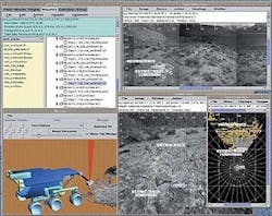
Rover softwareThe FIDO rover on-board computer runs the VxWorks 5.3 real-time operating system from Wind River Systems (Alameda, CA). This turnkey operating system is bootable from an on-board solid-state disk. It comprises a three-tier architecture that includes a device driver layer, a device layer, and an application layer. This architecture has proven robust and extensible during thousands of hours of operation. Code is written in ANSI C for modular portability and extensibility.The Web Interface for Telescience (WITS; Pasadena, CA) rover command software provides an Internet-based user-friendly interface for distributed ground operations during planetary lander and rover missions (see Fig. 2). It also offers an integrated environment for operations at a central location and for collaboration with geographically distributed scientists.
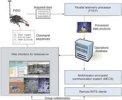
A FIDO rover field test evaluated operations scenarios for the upcoming Mars mission while using Internet-based operations enabled with WITS and multimission encrypted communication system (MECS) software (see Fig. 3). The MECS provided secure communications over the Internet. During the field test, scientists used WITS and MECS software to visualize downlink data and generate command sequences from five locations in the United States and one in Denmark. In the operations readiness tests leading up to the field test, university researchers in the United States controlled the tests from their remote locations.
During field trials, FIDO operations are directed by the JPL Mars mission flight science team and distributed to collaborative scientists worldwide via the Internet. They use the Web interface for telescience and the multimission encrypted communication system for sequence planning, generation, command, and data product recovery.
Company InformationField Integrated Design and Operations GroupPasadena, CA 91109www.fido.jpl.nasa.govJet Propulsion LaboratoryPasadena, CA 91109www.jpl.nasa.govWeb Interface for TelesciencePasadena, CA 91109www.wits.jpl.nasa.govWind River SystemsAlameda, CA 94501www.windriver.com


