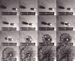
Imaging system freezes projectile collision
By R. Winn Hardin, Contributing Editor
Protective materials on spacecraft, airplanes, and vehicles endure a finite life in the harsh environments of both aerospace and military applications. Inevitably, they wear out or break down due to temperature and pressure extremes, external and internal stresses, or projectile bombardments. To save military and civilian personnel and equipment from these attacks, US researchers and scientists are constantly searching for newer materials to shield aircraft and spacecraft, as well as body armor, to protect military personnel. They are mainly exploring the strength of new materials, such as resistance to fracture, penetration by objects, and separation in the case of composite materials versus their weight.
In his materials investigations, Arun Shukla, professor at the University of Rhode Island (Kingston, RI), uses a high-speed DRS Hadland Ltd. (Tring, UK) Imacon 200 imaging system with gated microchannel-plate shutters, a fast-ramping xenon flashlamp, and continuous-wave laser illumination sources to capture the mechanism dynamics of projectiles striking protective materials during impact events that endure for just a few hundred nanoseconds. This system generates digital images that seemingly "freeze" bullet and other projectile trajectories in flight and during material impact. These images enable scientists to evaluate how Mach-type-speed sound waves that travel faster than the speed of sound and other high-speed dynamic events deliver damaging shocks to advanced composite materials.
Digital vs. film images
Previously, pictures of ballistics tests have been captured by high-speed-film-based imaging systems. The most advanced of these systems can collect upward of 1 million frames/s by positioning the film in a large arc within a camera and then exposing the film using a high-speed spinning mirror. After the film is exposed, it is shipped to an image-processing center for development. Then, it is returned for evaluation.
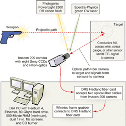
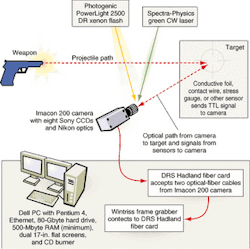
The high cost and the long time needed to process film are the main reasons why the university purchased the Imacon 200 imaging system for its materials experiments (see Fig. 1). "We can take the images and quickly dump them into a PC for analysis with the digital system," says Venkit Parameswaran, a postdoctoral fellow in the university's laboratory.
null
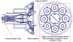
The Imacon 200 camera can capture as many as 16 images at speeds equivalent to 200 million frames/s using a special gated microchannel plate (MCP). It uses eight CCD sensors that functionally operate as a single camera in a "Gatlin-gun-type" operational configuration. Each sensor is triggered by one facet of a proprietary eight-sided, pyramid-shaped beamsplitter (see Fig. 2). The eight Sony Electronics (Park Ridge, NJ) interline-transfer ICX085 CCD sensors contain 6.7-sq µm pixels in a 1280 × 1024 array that are coupled via fiberoptics to eight DRS Hadland MCPs.
null
The plates are often used as amplifiers for night-vision and x-ray imaging systems. In this digital imaging application, however, the MCPs are used as fast optical switches or shutters that move from closed to open and back to closed positions within 5 ns with interframe pauses as short as 5 ns. Working with such short exposures, the system's intensifier gain capability enables the gray-scale pixel depth to achieve 10 bits. Each sensor's pixel information is embedded in a proprietary 16-bit packet along with header information, such as pixel location and exposure duration.
Each of the eight sensor imaging channels contains 5.6 Mbytes of built-in memory, enough to hold a 4-Mbyte frame while the next image is captured. Because of the CCD's read time, the system requires a 400-ns time gap between the first and second CCD images. However, by having eight CCDs functioning in succession and carefully controlling MCP operation, interframe rates between CCD images 1 and 2 can be as fast as 5 ns, explains DRS Hadland's application engineer Todd Rumbaugh. The camera comes with a standard lens mount; for this application, the cameras use a series of Nikon USA (Melville, NY) standard mount optics—some provided by DRS Hadland and others bought separately—that operate between 50 and 180 mm to focus the camera's single aperture on the region of interest.
Fast transfers
Image and data communications, including digital camera and shutter controls, are transmitted over two proprietary fiberoptic cables. Frank Kosel, DRS Hadland manager of sales and applications, comments that the company chose optical interfaces years ago because its high-speed cameras used in ballistics tests often had to be located a great distance from the host PC, and explosive events caused electromagnetic surges that would affect standard RS-232 transmissions.
The fiberoptic data channel operates at 19,200 baud, whereas the image-transfer channel operates at 200 Mbits/s. Consequently, the Imacon 200 system can quickly transfer its eight buffered images while reading a second set of images from the CCDs. "The fiberoptic system can run as high as 300 Mbits/s, but we only run it at 200 Mbits/s to match the other data rates in the system," says Kosel.
Optical-fiber cables connect the camera to a proprietary optical-fiber card, built by DRS Hadland, located in the host PC. This card is also connected, via a 9-pin cable, to a custom frame grabber that can accept digital data at 200 Mbits/s and feed the data across a PCI bus into the host PC's 512 Mbytes of RAM. DRS Hadland chose a custom version of the Wintriss Engineering (San Diego, CA) PCIHotLink Fibre Channel host-interface board because of its experience in developing high-speed imaging systems—often for military applications. The Imacon 200 system ships with a Dell Computer (Round Rock, TX) PC, which provides a Pentium 4 processor, hard drive, CD burner, Ethernet connection, and dual flat-screen monitors. One monitor shows the images from the camera; the other monitor is used for camera control via custom Imacon software.
"Our control software incorporates specific customer requests accumulated over the past 12 years," said Kosel. "Along with standard image-processing and camera controls, we have our own data-reduction software so we can calibrate the field of view to assign a certain distance value to a pixel. After calibration, we can go into an image and do distance, angular, and area measurements. Because the system knows the interframe time, we can determine velocity as well," he adds. "For distance and length-measurement calculations, explains Kosel, "we use the software that comes with the camera."
"We use it to measure the velocity of a projectile or the speed of a [target] crack," says university researcher Parameswaran. "When we want to gather more information about fracture mechanisms, we use MatLab routines from The Math Works (Natick, MA) to do the processing; they generate ASCII files that we put into other programs to calculate the numbers we need."
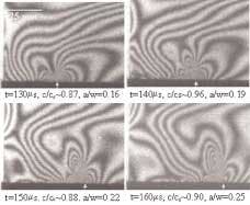
The Imacon software generates a single tif file that contains 16-Mpixel frames. Parameswaran says he typically saves the original tif image in a compact disk (CD) for archiving and then imports the file into Adobe Systems (San Jose, CA) PhotoShop to separate the frames and adjust the contrast and other image characteristics. Then, the individual frames are imported into custom modules developed in the laboratory using MatLab to determine various material characteristics, such as how fractures dynamically spread during projectile penetration or mechanical stress (see Fig. 3).
FIGURE 3. The University of Rhode Island has imaged the stress field around a subsonic crack propagating along the interface between orthotropic composite and isotropic materials. The stress field is obtained through an interferometric technique called photoelasticity, which uses a coherent light source for illumination. The sample is placed in a circular polarizer, (which includes a polarizer and quarter-wave plate placed on either side of the sample); a monochromatic filter is used along with the camera optics. This technique works in transmission mode for certain polymeric materials, whose refractive index changes when subjected to a stress field resulting in the formation of fringes. This full-field technique provides shear stress information at every point in the sample.
Triggering destruction
High-speed cameras that provide exposure times as short as 5 ns often work under extremely limited light conditions. To improve lighting results, university researcher Shukla uses special light sources. If an experiment calls for macroscopic illumination for regions of interest greater than a few inches, his team uses a Photogenic (Youngstown, OH) Powerlight 2500 DR xenon flashlamp with a 100-µs ramp time and millisecond flash durations.
null
The DRS Hadland software helps the researchers determine when the camera should be triggered so that the flash duration can cover a burst of 16 images (see above). Control signals pass through the fiberoptic channel from the host PC to the Imacon 200 camera; from there, they proceed across a 5-m-long wire to the xenon flashlamp.
Shukla has used a variety of sensors to trigger the camera. A dedicated analog input can trigger the camera on the rise or fall times of 2- to 50-V TTL signals from conductive foils or wires on the materials target that are broken on projectile impact or from photoelectric sensors that trigger the camera when the projectile breaks their beam.
For smaller regions of interest, a Spectra-Physics (Mountain View, CA) Millennium series continuous-wave laser operating in the green portion of the visible spectrum (523 nm) provides bright, collimated light for imaging without concerns about specific trigger timing. The camera provides eight 50-Ω TTL outputs to control multiple flash units or additional camera units. However, Shukla typically uses a single camera in his investigations.
DRS Hadland is currently improving the Imacon 200 system to include 14 framing channels and one streak channel. "This information would be extremely useful for impact and propagation studies because you can overlay the framing data on the streak and get a new understanding by adding time information," Hadland engineer Rumbaugh says.
