Light sources enhance imaging contrast
By Andrew Wilson, Editor
Although machine-vision illumination technologies vary widely from light-emitting diode (LED), to fluorescent, to fiberoptics, to cold-cathode fluorescent lamp (CCFL), their goal is ultimately the same: to enhance the contrast of an object under inspection so that the desired features are more easily identifiable. As light is reflected from surfaces of objects, a detectable contrast is created. Therefore, in choosing specific illumination or lighting products, it is important to understand which part of the light is absorbed and which part is reflected or transmitted to the input of the machine-vision system.

null
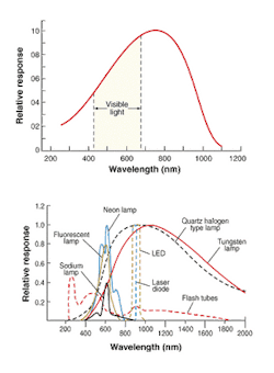
Spectral distribution is one of several ways in which light sources differ. This distribution of a light source must be contained within the spectral response of the image sensor (see Fig. 1). Light sources can also be classified according to their radiation pattern (point, linear, or hemispherical), distribution of light (spot, diffused, or collimated), geometrical shape, physical size, and efficiency. For an object or a feature to appear in an image, light coming from a light source must reflect off the object into the camera lens. Therefore, the object is seen differently when illuminated by different types of light.
Illumination sources also vary widely, including xenon flashlamps, fluorescent lamps, LEDs, and quartz halogen lamps. Each type of illumination source can be used in a number of different machine-vision applications.
Flashing and strobing
Flashlamps are high-intensity discharge lamps that are usually filled with xenon or krypton gas. When electrical current is conducted through the gas, these flashlamps produce optical radiation. Xenon flashlamps produce wavelengths from less than 50 nm to greater than 4 µm with high efficiency in the ultraviolet (UV) spectral region. In the visible region of the spectrum, these lamps generate about 150 to 250 lumens/W.
Xenon lamps are usually offered as either continuous-wave or strobe types. Continuous-wave xenon lamps are used in machine-vision applications where continuous light and a good color balance are required. Pulsed xenon systems can produce in excess of 250,000 candelas. In comparison, currently available LEDs typically provide intensities measured in the tens of candelas.
For many years, xenon-strobe illumination systems have been used in machine-vision systems to provide high-intensity, short pulsewidths and a wide spectrum of radiation. Such features improve the contrast of captured images, increase the depth of field of the imaging scene, and shorten camera-integration times.
null
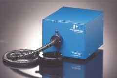
The X-Strobe series of strobes from PerkinElmer (Wellesley, MA, USA), for example, uses xenon strobes to freeze motion with high-intensity, short-duration pulses (see Fig. 2). When coupled to a charge-coupled-device (CCD)/charge-injection-device (CID) camera system, the strobe freezes object motion, which eliminates blur and enhances image quality. Several variations of the X-Strobe series are available; each optimized for maximum light output within a range of flash rates.
Low-cost fluorescents
Fluorescent tubes are generally low-cost, medium-life devices used for large-area backlights and front floodlights. Long lengths of fluorescent lights are often used in linescan web-inspection applications. Manufacturers of fluorescent lamps used specifically for machine-vision systems generally add phosphorescent material to improve the light output and stability. These lamps offer reasonably good illumination consistency, low temperature, and a long lifetime. Fluorescent lamps are available as linear- or ringlights. When used in machine-vision systems, the ballast for driving the fluorescent bulb must be a high-speed type so that it does not interfere with the acquisition rate of the camera.
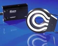
One example of a dual-circular fluorescent illuminator, the Superlight Model 18 from StockerYale (Salem, NH, USA), uses two independently controlled circular lamps (see Fig. 3). This dual-circular lamp unit provides 360° of uniform illumination for industrial imaging and machine-vision applications.
null
Each illuminator is supplied with an adapter for attachment to microscopes and cameras. Standard lamps include white color temperatures, black light (UV), and other wavelength-specific colors, including red (685 nm), yellow (585 nm), green (544 nm), and blue (450 nm). Superlight Model 18 operates at 25 kHz for flicker-free illumination. Each lamp can be controlled independently by a separate power switch; this allows operators to control the output intensity or field of illumination to fit specific application requirements.
LED illumination
In machine-vision applications, selecting the necessary type of lighting largely depends on the size, surface features, and geometry of the part to be inspected. In many machine-vision systems, LED lighting can be used in several configurations, including ringlights, spotlights, backlights, and diffuse lights (see Vision Systems Design, May 2000, p. 55). Even in specifying a ringlight, however, the systems integrator must fully understand the type of product being inspected.
According to Ryugo "Luke" Sakoda of the application engineering department at CCS America (Waltham, MA, USA), when the company's LDR-70A-W (wide) and LDR-70A-N (narrow) LED ringlights image an object at the same distance, the effect is dramatic. He notes that Type W lights the entire view comparatively uniformly because it has a wide light area.
"Because the narrow type is more focused, you can obtain a higher intensity in a longer distance compared with the wide type," says Sakoda. "But you can only see a smaller field of view (FOV). Because the wide type illuminates the image over a wider range, you can see a larger FOV compared with the narrow type. But the distance between the light and work piece should be shorter to get the same level of intensity as the narrow type," he adds.
Web inspection
Tungsten-halogen lamps are incandescent lamps that use a quartz capsule containing a filament and a halogen gas. The small capsule size allows the filament to operate at a high temperature, which produces light at a higher efficiency than standard incandescent lamps. Because the filament is relatively small, tungsten halogen lamps are often used where a highly focused beam is desired. In addition, tungsten-halogen lamps generally produce a whiter light than other incandescent lamps, are more efficient, last longer, and provide improved lamp lumen depreciation.
Mike Muehlemann, president of Illumination Technologies (East Syracuse, NY, USA), says, "When operated at full intensity, the output from a standard tungsten-halogen lamp has a color temperature of about 3200 K. This lamp's output is smooth and continuous with no spikes or dips in the spectra, and its 3200 K color temperature provides high output at the red end and low output at the blue end."
To power its range of fiberoptic Lightlines for web applications, Illumination Technologies supplies both tungsten-halogen and metal-halide light sources. Whereas the tungsten-halide sources are used for stable, high-intensity applications, metal-halide lamps provide a white light for up to 10,000 hours. These one-piece units are powered by a three-feed-line design that is evenly distributed across the length of the 1-m light line for lighting uniformity. For industrial environments, the modular light-line system can also be supplied in sealed NEMA 12 enclosures to keep out dirt, debris, and vapors.
The methods by which lighting is used must also be considered (see "Using machine vision to inspect lighting components," p. 36). Integrators must take into consideration such factors as front or back illumination, lightfield or darkfield techniques, and the use of filters and polarization methods. Most lighting and illumination suppliers provide helpful technical articles, charts, techniques, and application notes on their Web sites.
For information on suppliers of lighting and illumination equipment, see the Vision Systems Design Buyers Guide, February 2003, p. 65.
Using machine vision to inspect lighting components
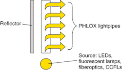
Last year, backlighting supplier Phlox Corp. (Provence, France) obtained several patents based on its edgelit-backlight lightpipe technology initially developed for LCD backlighting applications. Now, the company has diversified the use of this technology with 10 standard products developed for machine-vision applications (see Vision Systems Design, August 2002, p. 9).
For automated quality control of these products, the company has developed a video analysis system that controls product quality, uniformity, and luminance. Installed in a darkroom, the video analysis system uses two CCD cameras. One camera is an A11 from JAI (Copenhagen, Denmark), which is fitted with a 12-mm-focal-length lens from Tamron (Commack, NY, USA) and used for surface and uniformity inspection.
null
The second camera is an XC-711 from Sony Electronics (Park Ridge, NJ, USA), which offers a 50-mm-focal-length lens to calculate the dimensions of the part. The two cameras are connected to a PC equipped with custom image-processing software.
For each inspection, the serial number of the inspected product, the initials of the operator who performed the final inspection, and the results of the inspection are automatically saved in a specific file. By modifying the camera's shutter and aperture, the luminance variation from one lighting device to another can be adjusted. Measurements are made for each pixel to ensure the reliability of the results and detect irregularities of the lightpipe.
To obtain reliable luminance-uniformity measurements, the software compensates for the camera len's angular aperture. By displaying the pixels in different colors, the software detects problems concerning the coupling of the light source with the lightpipe, or other problems. The software also analyzes each line or column to monitor the manufacturing process for each lightpipe. This allows tracking of each manufacturing process stage and allows operators to identify in which stage problems have occurred.
Company Info
CCS America www.ccs-inc.co.jp
Illumination Technologies www.illuminationtech.com
JAI www.jai.com
PerkinElmer www.perkinelmer.com
Phlox Corp. www.phlox-gc.com
StockerYale Inc. www.stockeryale.com
Tamron www.tamron.com
Sony Electronics www.sony.com/videocameras