By C. G. Masi, Contributing Editor
A manufacturer of cast-aluminum automobile wheel rims faced numerous design challenges when it decided to automate its production process. The company often runs as many as a dozen different rim types simultaneously on its production line, out of more than 50 types.
The production of wheel rims starts in the casting factory, where several molds are set up to cast a particular type. All the casting lines feed the rims onto a common roller conveyor, which carries the rims to an inspection/sorting system. Complicating the process, however, is that the mix of rims placed on the conveyor is unpredictable, as is the order in which they come down the conveyor.
The inspection/sorting system flags the rims electronically according to part number and passes that information to a pick-and-place robot. Based on received information, the robot picks the proper rims off the conveyor and places them on to the correct finishing line. There are 12 finishing lines, each set up to receive and complete wheel rims of a specified part number.
Obviously, the finishing machines must receive only the rims of the type they are set up to handle. Rims have different widths, diameters, number of spokes, and profile shapes. If a rim ends up on the wrong finishing line, it could be damaged, and, worse, it could damage the finishing machines. Therefore, the inspection/sorting system must not pass a rim to a finishing machine until it has positively identified the rim by its correct part number.
Positively identifying rim part numbers appears to be a straightforward process for an automated electronic inspection/sorting system. However, the rims exit the casting process with different mold marks, color differences, and flashing between spokes that complicate the identification process. These variations prevented the automated electronic inspection/ sorting system from achieving a 100% accuracy inspection. As a result, production engineers had to insert an escape line for those rims that proved too difficult for the automated system to identify. These rims were manually checked by human inspectors for the correct part number. Then, the rims were manually returned to the proper finishing line.
After a few years of operation, the automated electronic inspection/sorting system positively identified rims only 60% of the time. This inspection deficiency resulted in widespread labor-intensive manual sorting, cost inefficiencies, production delays, and low yields. It also posed other difficulties. In addition to the high mixture of rims, new types were constantly being added to the production line. To set up the automated electronic inspection/sorting system to recognize new rim types, production engineers had to first run the rims through a duplicate sorting system, teach the system to recognize the new rim types and their variations, and then download the new information to the production-line inspection/sorting system. This new-rim teaching process took an unacceptable two-to-three hours to accomplish.
Faster and smarter
To overcome these production problems, the wheel-rim manufacturer turned to systems-integrator Wineman Technology (Saginaw, MI, USA) for an automated vision-inspection/sorting solution. Wineman had to develop this new system based on the following specifications: better than 95% positive identification; no false identifications; fewer than 5 s for inspecting a rim; faster and easier teaching of new rim types; and seamless fit into the existing automated system.
"We could have a few rims come up as undetermined, but we could never send a rim down the wrong line," adds Wineman test systems director Matthew Eurich. The Wineman design team built and installed the new vision-inspection/sorting system in eight weeks. System installation on the production line took less than 24 hours.
Wineman senior engineer Jeffrey Jenkins and Eurich credit the fast development and installation times to cooperation from the client and a user-friendly software-development environment. While Wineman engineers had worked extensively on vision applications before, the applications were not as complicated, nor similar enough, to provide useful code blocks.
"We were fortunate that the client sent us a lot of wheel rims for examination, and we were able to run the system through its paces on our floor," Eurich says. "That significantly shortened the installation time. If we didn't have the system up and running within 24 hours, it would have seriously impacted the client's production that week."

FIGURE 1. Vision-inspection/sorting system for identifying automobile wheel rims moving on a conveyor line comprises two cameras, various lighting devices, personal computer, and vision boards and software. One camera images the wheel rim's face surface and the other images the rim's edge profile. Fluorescent tubes illuminate the rim's face, and a red LED backlight illuminates the rim's profile. All acquired images are passed to a vision card installed into the personal computer. Using vision software and an imaging database, the computer identifies the rim by part number and directs the pick-and-place robot operation.
While Jenkins was doing the mechanical design and specifying the hardware, one or two programmers were writing code. The resultant vision-inspection/sorting system includes two cameras, fluorescent lighting, LED backlighting, and vision boards, and software that are interfaced to the existing identification system (see Fig. 1). Equipment in the existing system includes a material-handling personal computer with custom software, an Allen-Bradley (Milwaukee, WI, USA) PLC5/60 programmable logic controller, and a Fanuc Robotics America (Rochester Hills, MI, USA) pick-and-place 430i robot.
During the new vision-inspection system design-and-development process, a stationary stand was used to represent the conveyor belt (see Fig. 2). Two vertical rods welded to the stand located the wheel rim in three dimensions for the two cameras. One of the rim's circular edges stops against the two pins. These two points on the circumference are sufficient to locate that edge and, therefore, the rim's center on two horizontal axes. The conveyor height, of course, locates the wheel's bottom edge in the vertical direction. The location of the top edge depends on the rim's thickness.

null
Positioned in the stand, the rim sits correctly for one camera to image the rim's face surface and one camera to image the rim's edge profile. However, the vision-inspection/sorting system cannot locate the rim's angular orientation around the vertical axis. Consequently, the vision system must make that determination in software.
System details
Using a 6-mm lens from Fujinon Inc. (Wayne, NJ, USA), a TM-200 CCD camera from Pulnix America (Sunnyvale, CA, USA) looks down on the wheel rim's face surface from a height of approximately 24 in. (60 cm) above the conveyor belt (or stand). This height above the rim's face, however, varies from 12 in. (30 cm) to 18 in. (45 cm) according to the rim width. Illumination for the face image comes from four 24-in. (60-cm) ISDFL-23 high-frequency fluorescent tubes from DVT Corp. (Norcross, GA, USA) arranged in a "ring" configuration within a square-mounted panel positioned about half way between the camera and the rim. "We wanted to use a regular ringlight," says Jenkins, "but couldn't find one big enough."
Instead of operating at 60 Hz, as ordinary fluorescent lights do, the vision system fluorescent lights operate at 900 Hz. The face-imaging camera runs at 30 frames/s, so the fluorescents' flicker at 60 Hz would have caused unpredictable illumination variations. At 900 Hz, the fluorescent lights produce no flicker artifacts.
Positioned to one side of the wheel rim, a second TM-200 CCD camera from Pulnix uses a Tamron USA (Commack, NY, USA) 8-mm lens to acquire profile images that help determine the rim height. Both cameras contain a 768 × 494-pixel array that acquires 0.39-Mpixel-resolution images. Whereas different wheel types offer different profiles, the rim's face shape provides more useful diagnostics than its profile details. The face image, however, cannot determine the rim width.
To measure the rim height, the design team placed a 3 × 6-in. red LED backlight from Advanced Illumination (Rochester, VT); this setup projects a light beam past the rim edge into the camera lens. A red filter strips out most of the white stray light from the rim's face-illumination system and from ambient light. The backlighting arrangement provides a profile image that is independent of the rim's surface coloration and diameter.
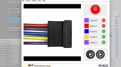
The acquired camera images are directed to a National Instruments (NI; Austin, TX, USA) PCI-1409 frame-grabber board, which is slotted into a commercial personal computer running Windows 2000 software. The computer uses an image-analysis application built around NI's IMAQ Vision software to measure the rim diameter from the face image and the rim width from the profile image. The part-management screen displays the wheel rim's face and profile views (see Fig. 3).

null
The vision-inspection/sorting system uses these measurements in case it can't make a positive identification of a wheel rim. Armed with data that define the rim diameter and width, the pick-and-place robot then knows when and where to grab an unidentified rim and move it to the escape line.
After measuring the rim's diameter and width, the computer tries to match features in the face image with those of rim face images stored in its database. Since it has received the rim's height and diameter, the computer looks at patterns for rim types that match those parameters. It looks at a spoke profile, a hole profile, and a half-rim profile (see Fig. 4). Then, it scores these profiles on a scale from 0 to 1000 and adds the scores. To grade a positive identification, this total score has to match the database score within 10%. Otherwise, it's classified as "Unidentified."

FIGURE 4. Spoke profile is one screen pattern the vision-inspection/sorting system uses to identify a particular wheel rim (top). Pattern-matching software score three key areas of an image on a scale of 0 to 1000. The system also looks at the shapes of the holes between the spokes (bottom). This wheel rim presents an identification challenge in that the holes are not all the same size and shape. Color variations and bits of mold flashing between spokes are variables that complicate rim identification.
The vision-inspection/sorting system has achieved better than a 99% identification score for checking wheel rims, made no misidentifications, and identified wheel rims within 5 s. Moreover, system-training time for new wheel rims has been cut from two to three hours to approximately five minutes.
Company Info
Advanced Illumination www.advancedillumination.com
Allen-Bradley www.ab.com
DVT Corp. www.dvtsensors.com
Fanuc Robotics America www.fanucrobotics.com
Fujinon Inc. www.fujinon.com
National Instruments www.ni.com
Pulnix America www.pulnix.com
Tamron USA Inc. www.tamron.com
Wineman Technology www.winemantech.com