System helps prepare sintered metal parts
Diverse parts for the automotive industry are processed by a robot, machine-vision system, PLC, and network control.
By Mary Kay Morel
The GKN Sinter Metals production facility in Salem, IN, USA, uses a sintering process to produce transmission parts and power-steering components for major automobile manufacturers and their suppliers. In 2001, the company automated a production line that makes six sizes of transmission clutch plates for commercial vehicles such as trucks and school buses. The robots and integrated vision system in this production line enable it to run additional parts such as mechanical diode sets for transmissions—all without the need for manual changeover.
"Flexibility of the robots has been important in accommodating multiple parts. This is a continuous line, but we run multiple types of parts in a batch-type situation," says Gale Wiseman, electrical engineering supervisor at the Salem plant. "We might need 30,000 or so parts to meet production requirements for the month, but we might run batches of 5000 to 8000 parts at a time to meet the just-in-time needs of our customers. Changeover of the dies in the press takes less than two hours. Changeover for the robotic line involves simply selecting a different program to run."
In the sintering process, powder-metal parts are formed to near-net shape in high-compression presses and then baked in furnaces to produce the final automotive parts. At the GKN facility, every 6 to 8 s a compacting press made by Cincinnati Incorporated automatically ejects a newly formed powder-metal part from its dies onto a Shuttleworth low-pressure accumulating conveyor. After a brushing operation removes any loose powder, the part transfers to an Ohaus CQ10R31 weighing station, where it is checked against a known weight.
The conveyor and weighing operations are controlled by an Allen-Bradley SLC/504 PLC (programmable logic controller) that also interfaces with the press, robot, vision system, and other automation components. Parts are 9 to 10 in. in diameter and weigh approximately 3 to 4 lb each. "We do a 100% weight check on the parts, and results are fed back into the press, which makes real-time process adjustments," says Wiseman. "Parts that fail the weight check are diverted down a reject spur."
To the naked eye, parts coming down the conveyor look like they are all oriented the same way. However, orientation varies slightly, and positioning accuracy is extremely important for the processes that follow. "This is where the vision system comes in," Wiseman explains.
Part orientation
Parts that pass the weight check and reach the U-shaped stop encounter a photo eye connected to a PLC. The PLC signals the Motoman UP20 robot and monochrome Cognex In-Sight 2000 vision system that a part is present and ready for pickup and eventual loading onto a conveyor belt that delivers it to the furnace. The vision system has a 1/3-in. CCD and an 8.5-mm C-mount lens, which provides a field of view of approximately 12 in. to accommodate the part sizes and any positional deviation on the conveyor.
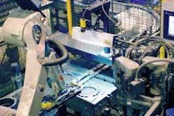
Motoman engineers chose a Phoenix Imaging Model 2010 high-frequency fluorescent light source to minimize the natural 60-Hz flicker of the ambient lighting and provide a more consistent continuous light source (see Fig.1). To calibrate the system prior to running production, the engineers used a custom jig to teach the vision system x-y directions in relation to the zero (home) position. This jig also defines the pixels-per-millimeter count, based on field of view.
During production, the robot will not move until the vision system verifies that the part it sees matches the part that the PLC indicates the line should be running. The PatFind part-location tool from the Cognex image-processing library indicates the presence of a part and location of all of the key features of the part. The vision system finds multiple features such as specific gear teeth that are unique to that part. For each pick, the vision system calculates the "best" feature to use for part orientation. It chooses the feature that requires the robot to make the least amount of angular correction.
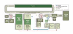
The In-Sight 2000 vision system uses a circle-find edge tool built into the Cognex library to find the center point of the part. That point is converted to an x-y coordinate used by the robot. The PatFind tool also finds the centerpoint of the "best" part feature. The vision system calculates the angle between the x-y center point of the part and the center point of the part's best feature to determine the part's rotation from the zero position, which was determined during the calibration step. The x-y coordinate and angle orientation are sent from the vision system, through a CDN366 DeviceNet interface module and across the DeviceNet network to a Motoman JARCR-XFB01B DeviceNet network card in the robot controller (see Fig. 2).
The robot uses the information from the vision system to calculate its approach path and the pick location. It does all the calculations for the pickup location and then places the part into the known fixed location on the custom drill nest. The robot precisely places the other part types that do not require drilling in multilayered stacks onto individual ceramic disks at a loading station.
The vision system does not communicate with the PLC directly. Instead, the robot interfaces with the PLC and the other automation equipment using a MARIO (Motoman Allen-Bradley Remote I/O) card in the robot controller. Allen-Bradley's Flex I/O modules are used throughout the conveyor and drill system, and a Panelview OIT located at the PLC is used for visual system and setup control. A second Allen-Bradley SLC/504 PLC controls the drilling operation, outfeed conveyors, and transfer operations. Both PLCs communicate with plant networks via Ethernet.
Once the vision-system algorithms determine the precise orientation of the part, the robot rotates one side of its electromagnetic dual end effector, custom made by Motoman, to enable it to pick up the part in the precise orientation needed for the next operation. "The sides of the robot end effector are identical and use a three-point electromagnetic pickup point. We did not want to use a gripper that would apply pressure and might break or chip a tooth," says Wiseman.
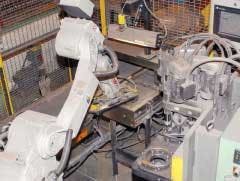
Compacted parts are still fragile at this point, because they have not been heated in the oven to bond the powder particles. To pick up the compacted part without causing chipping or breaking, the robot moves one side of the end effector to within approximately 1/16 in. above the part before energizing the three electromagnets. To set the part down, the robot again moves to within about 1/16 in. from the part nest or ceramic disk and then reverses the polarity of the electromagnets. Reversing the polarity provides a little bit of energy to expel the part and causes it to drop evenly, as opposed to turning off the power to the magnet, which can cause the part to drop unevenly. It also aids in keeping loose powder from building up on the magnets (see Fig. 3).
Depending on the part type, the robot loads the part into the custom drill nest or precisely stacks the individual parts in multiple layers onto ceramic disks on the outfeed conveyor. When processing parts that need to be drilled, the robot picks up a part from the U-shaped stop on the infeed conveyor using one side of the dual end effector, then rotates and moves to the drill nest on the Sugino SN3 drill. There, the robot picks up a drilled part using the other side of the end effector, rotates and places a new part into the drill nest from the first side, and signals the second Allen-Bradley PLC to initiate the drill machine to cycle. Finally, the end effector rotates and the robot stacks the drilled part from the second side onto the ceramic disk.
Parts must be perfectly aligned and positioned absolutely flat on the ceramic disks when they go through the furnace. This is particularly critical when the process requires that several parts be stacked in a common orientation before going into the furnace. Once the required stack height on the ceramic disk is reached, the second PLC signals a pin stop on the conveyor to release the loaded ceramic disk. The disk transfers to the front of the furnace and make a 90&#deg; transfer onto a staging station. Hard-tooled fixtures line up stacks of disks for loading into the furnace. A pop-up chain conveyor transfers the row of loaded disks to the conveyor belt. The furnace belt moves at a part-specific speed through the furnace, where the parts are sintered.
After the sintering process is complete, a Motoman UP130 robot equipped with a custom gripper unloads components from the oven, performs a dipping operation for rust inhibition and lubrication, and then stacks them in part-specific configurations into wire baskets. In this closed-loop system, ceramic disks recycle back to the load operation on Shuttleworth nonfriction conveyors.
MARY KAY MOREL is staff writer/editor, Motoman, West Carrollton, OH, USA; www.motoman.com.
Company Info
Cincinnati Incorporated, Cincinnati, OH, USA, www.e-ci.com
Cognex, Natick, MA, USA, www.cognex.com
GKN Sinter Metals, Auburn Hills, MI, USA, www.gknsintermetals.com
Motoman, West Carrollton, OH, USA, www.motoman.com
Ohaus, Pine Brook, NJ, USA, www.ohaus.com
Phoenix Imaging Machine Vision Systems, Livonia, MI, USA, www.phoeniximaging.com
Rockwell Automation, Milwaukee, WI, USA, www.rockwellautomation.com
Shuttleworth, Huntington, IN, USA, www.shuttleworth.com
Sugino, Schaumburg, IL, USA, www.suginocorp.com


