System tests and calibrates instruments
In eight weeks, Soliton developed a calibration and inspection system for automotive instruments.
By Andrew Wilson,Editor
Multipoint inspection of multiple automotive gauges in modern electronic-instrument clusters requires a seamless combination of machine-vision and test-and-measurement equipment. Engineers at Soliton Technologies have combined off-the-shelf data-acquisition, I/O, and machine-vision equipment to measure and calibrate these gauges.
Started six years ago, Soliton Technologies has grown from three people to one of the largest machine-vision-system developers in India. Employing more than 50 people, the company now has offices in Bangalore, India, as well as Milwaukee, WI, USA, and supplies companies such as General Electric, Intel, IBM, and Ford Motor Company. Soliton’s systems are being used in the automotive, food, textile, and pencil-manufacturing industries for various inspection and sorting applications.
In 1998, Soliton began working with Pricol Limited, one of India’s manufacturers of automotive instruments, to develop a fully automated vision system for calibrating speedometers. After studying more than 100 different speedometer models that Pricol manufactured, Soliton developed a flexible image-processing algorithm for accurately reading the needle position on the speedometers and other types of gauges.
This algorithm was implemented using LabVIEW and IMAQ Vision image-processing tools from National Instruments (NI). The software, called GaugeVIEW, has since been used to build various inspection and calibration systems for all kinds of automotive gauges and clusters.
Recently, Pricol required a calibration and inspection system to check the gauges on its new generation of instrument clusters. The requirement was demanding in terms of accuracy, speed, and reliability and was met by Soliton using a multicamera vision system.
TEST AND MEASUREMENT
“Pricol wanted an automated test system that had a complete test time, including the loading and unloading of the instrument cluster, of less than a minute,” says Anand Chinnaswamy, director and chief technology officer of Soliton. “Because there was no backup test system, we needed to design a system with little or no moving parts with a high mean time between failures. And, because new instrument clusters would need to be inspected, the system needed to be reconfigurable and expandable with controller-area-network interfaces.
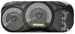
Four gauges and a liquid-crystal display (LCD) had to be inspected on the instrument cluster (see Fig. 1). These four gauges indicate vehicle speed, engine speed, fuel level, and engine temperature. Each gauge is driven separately by a microstepper motor driven by an on-board controller and based on signals received from respective sensors. To test the instrument cluster required that initial checks be performed on the controller to determine whether the LCD display operates correctly and that the gauges be calibrated at different ranges. This is followed by a multipoint inspection to ensure proper calibration.
“In an alternate design that Pricol considered, a single camera with motion-control hardware was used to monitor the four gauges,” says Chinnaswamy. “Our design used multiple FireWire cameras with no motion control, allowing each gauge to be tested in parallel to reduce cycle time, and the low cost of the FireWire cameras allowed us to reduce the total cost of the system.”
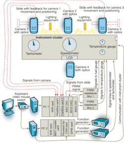
Positioned over the four gauges, four DFW-VL500 FireWire cameras from Sony were interfaced to a PCI backplane using two FireWire interface cards from Unibrain. To accommodate different gauge-center distances, the cameras were mounted on manually operated slides equipped with rotary potentiometers that indicated position to the software through a PCI-6014 DAQ board. “Because each camera features a 12X motorized zoom that can be controlled over FireWire, different instrument-cluster models can be accommodated,” Chinnaswamy says. To configure camera parameters such as zoom, focus, shutter speed, and filter, Soliton used the NI IMAQ 1394 driver.
Because of the large number of cards in the system, two 10/100 BaseT networked 2.4-GHz Pentium 4 computers were used (see Fig. 2). “Although the system could have been designed using a single 13-slot PXI chassis,” says Chinnaswamy, “the cost would have increased dramatically. For example, while the cost of a single PCI-based FireWire card is less than $50, the cost of a PXI-based equivalent would have been around $500.”
TEST GENERATORS
Two 33220A function generators from Agilent Technologies were used to drive the speedometer and tachometer in the instrument cluster. Controlled from a National Instruments PCI-GPIB card, these provided square- and sine-wave signals with amplitudes of 20 V pk-pk at 20 mA and frequencies up to 15 MHz. “Although we would have liked to have used NI’s PCI boards to perform these functions,” says Chinnaswamy, “we needed the higher voltage output of the Agilent generators. The maximum output of NI’s cards at the time was 10 V pk-pk at 20 mA.”
“The calibration of precision frequency sources requires comparison between the device to be calibrated and a precision reference source,” says Chinnaswamy. Thus, to calibrate each individual instrument cluster, it was also necessary to generate a reference signal separate from the timing generator. Using reference signals from an NI PCI-6601 timing and digital I/O board, a pulsewidth-modulation (PWM) pulse train was sent at a specified frequency and duty cycle to the cluster, and the gauge was then imaged by the corresponding camera.
Both the fuel and temperature gauges of the instrument cluster were controlled from PWM signals generated by counters on an NI PCI-6014 data-acquisition board or from resistors selected from a decade resistance box. The decade resistance box was built using off-the-shelf resistors switched under software control through NI PCI-6503 and NI PCI-DIO-96 digital I/O boards. A custom-built algorithm was used to select appropriate resistances and provide closed-loop control over resistance within 0.1 Ω.
While the original system had a custom resistance box built by Soliton, the company has recently upgraded the system using an off-the-shelf resistance box from IET Labs, formerly GenRad. “Because change in resistance over temperature can affect measurement accuracy,” says Chinnaswamy, “we decided to implement a higher-precision resistance-measurement system.”
AUTOMATED PROCEDURES
Each test process begins with a series of checks, called initial data checks, that are performed through the cluster controller system. Each LCD is checked by sending commands to display characters on the LCD and imaging these characters with a FireWire camera. This is followed by a zero-point-detection (ZPD) check on all four gauges in parallel. To do this, the system sends a command to the cluster controller to move the gauge pointer to the initial position. The system then acquires an image and sends respective pointer position offsets, if any, to the cluster controller.
After ZPD alignment, the system simultaneously calibrates all four gauges. The speedometer and tachometer are calibrated by sending a specific pulse train to the cluster and imaging the gauge using the corresponding camera. Pointer readings are then compared to standard input frequencies. If there are any offsets, correction coefficients are computed and sent to the cluster controller’s CPU where they are stored in EEPROM.
Fuel and temperature gauges are calibrated in a similar fashion, except that the inputs to these gauges are PWM signals or resistance values. This calibration is followed with an inspection, during which the system sends the required inputs to the four gauges and checks the readings to ensure they are in range. The system performed this calibration and inspection process at several points for each gauge.
SOPHISTICATED SOFTWARE
GaugeVIEW is the core software used in the application. The needle detection and reading algorithm implemented in GaugeVIEW can automatically correct for offsets and rotations of the gauge in the image. In fact, GaugeVIEW can read the gauge even when it is upside-down in the image, without compromising accuracy. A gauge can be read with an accuracy of 0.5°, using a standard 640 × 480-pixel camera. Greater accuracy can be achieved using higher-resolution cameras. The latest release of GaugeVIEW v7.0 can take advantage of color information to get the full contrast between the needle and the background.
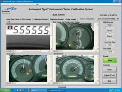
Soliton needed many low-level algorithms such as thresholding, filtering, and edge detection and high-level pattern-matching tools to implement the algorithm and found efficient implementations of all these in IMAQ Vision. The user interface for registering the different clusters with the application, the runtime software to handle the serial communication with the cluster, GPIB control of the signal sources, and the image-acquisition and processing were all written in LabVIEW (see Fig. 3). Says Ganesh Devaraj, managing director of Soliton, “The productivity gains achieved by using LabVIEW and the integrated hardware drivers for image acquisition, data acquisition, and instrument control reduced our development time significantly.”
As a result, within eight weeks, Soliton built a fully automated PC-based test system for automatic calibration and inspection of instrument clusters.Company Info
Agilent Technologies, Palo Alto, CA, USAwww.agilent.com
IET Labs, Westbury, NY, USAwww.ietlabs.com
National Instruments, Austin, TX, USAwww.ni.com
Pricol Limited, Coimbatore, Indiawww.pricol.com
Soliton Technologies, Bangalore, Indiawww.solitontech.com
Sony, Park Ridge, NJ, USAwww.sony.com/videocameras
Unibrain, San Ramon, CA, USAwww.unibrain.com


