Peripherals team to test microdisplays

Off-the-shelf PC-based image-processing and motion-control components rapidly analyze LCOS microdisplays.
By Andrew Wilson, Editor
In contrast to active-matrix, flat-panel LCDs, in which the liquid-crystal material is sandwiched between two glass plates (one with thin-film drive transistors at each picture element), liquid-crystal-on-silicon (LCOS) microdisplays sandwich the liquid crystal between a single glass plate and an IC. Circuits that control image formation are fabricated on the IC, which is coated with a reflective surface. Polarizers located in the light path both before and after the light reflects from the chip allow these devices to be used as miniature reflective displays.
"Unlike transmissive devices produced by companies such as Kopin, where additional circuitry is needed at each pixel site," says Lewis Collier, president of DisplayCheck, "reflective devices have a large fill factor making the displayed image less pixilated because the circuitry is behind each pixel and does not create an obstruction in the light path." This also enables LCOS microdisplays to scale to higher resolution because more pixels can be etched into a smaller chip area.
Microdisplays are now produced by a number of companies including Brillian, Hana Microdisplay Technologies, and Microdisplay. Current product applications include rear-projection HDTV, head-up displays, cell-phone eyepieces, PDAs, and videophones.
To build these products, designers often use a number of LCOS microdisplays in miniature display engines. In rear-projection HDTV, for example, three devices—each tuned for a specific color—can be used in display engines to reflect incoming light at either red, green, or blue (RGB) wavelengths. The resulting RGB image is then optically collimated to form a projected color image.
Before shipping the LCOS microdisplays, however, each of the devices must be tested for specific defects. "In the past," says Collier, "the parts were mounted on prototype display engines, manually aligned and focused, and the resulting images examined for defects such as white and dark spots." Not only was this process extremely tedious, it was prone to human error. Worse, such tests could not quantitatively describe the brightness, uniformity, contrast ratio, flicker, response time, and pixel defects of each device.
Founded in 1998, DisplayCheck builds systems that automate the process of measuring the characteristics of LCOS microdisplays. "Because these parts cannot be passively examined," says Collier, "it is necessary to actively drive each part as it is being tested."
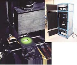
DisplayCheck works with several LCOS microdisplay vendors to integrate test drivers for each device. In the design of the company's MDT-250 Series, each device is attached to these drivers and placed under an optical stage (see Fig. 1). In addition to measuring factors such as brightness and uniformity, the system also measures response time, flicker, color coordinates, color temperature, and spectral reflectance.

Several methods are used to perform the tests. While measuring the brightness and uniformity can be performed optically with either a CCD camera or a spectrometer, a photodiode is used to analyze response time and flicker. Color coordinates and spectral reflectance are also measured by a spectrometer. In the development of the optical head, a number of off-the-shelf components are used in addition to the custom-designed high extinction-ratio optics assembly (see Fig. 2).
OPTICS DESIGN
The optical switching of each LCOS microdisplay is based on polarized-light switching. Incoming white or color-filtered light from a light source built by Illumination Technologies is polarized and reflected onto the device's surface by a polarizing beamsplitter (PBS). As the polarized light is reflected back from each pixel, its polarization can be changed, depending on the image being displayed on the device. After passing through the PBS, the light passes though another polarizer and an optical beamsplitter, where it is detected by a CCD camera. Because the reflected path through the PBS and the second polarizer is 90° out of phase with the first polarizer, the detected light captured by the camera provides a measure of the gray level of each pixel.
Light reflected from the optical beamsplitter then passes through a second beamsplitter, where it is reflected to both a USB-2000 spectrometer from Ocean Optics and a photodiode array from Thor Labs. "To automate the testing of these devices," says Collier, "it was necessary to build a system that combines machine vision, data acquisition, and motion control."
To digitize the reflected light from each of the pixels of the LCOS microdisplay, it is necessary to locate the part within the field of view of the system. Once located, the reflected light from each pixel must be detected. "If only a single high-magnification camera with a small field of view is used, it takes a long time to measure the whole LCOS display for macroscopic measurements such as brightness, contrast ratio, and uniformity," says Collier. "In addition, the single optics assembly cannot be optimized for the dual roles." Because of this, DisplayCheck mounted two Adimec 1000 × 1000 MX12P CCD cameras above a Danaher Motion 6-in. x/y/z/f stage.
The first camera is fitted with either an f/2.5 zoom macrolens from Thales Optem or an f/1.9 fixed-magnification Xenoplan lens from Schneider Optics. Using either of these lenses, a variety of parts ranging in pixel formats from 600 × 400 to 1920 × 1280 can be examined at a working distance of less than 3 in. from the device. The customer can select the lens option that best suits his/her needs.
The second camera is fitted with either an off-the-shelf 6.5X zoom lens from Navitar or a fixed-magnification lens from Thales Optem that was customized under research sponsored by the United States Display Consortium to use polarizers from Moxtek. The high-resolution optical assembly locates the individual pixels and subpixels of the part. "This allows the system to measure part defects as small as 1 µm," says Collier.
According to Collier, the Adimec MX12P was chosen because of its good quantum efficiency across the spectrum and its 12-bit dynamic range. "Because the system was required to measure parts with a contrast ratio on the order of 3000:1," says Collier, "we needed a camera with a high dynamic range. Other factors included the low number of pixel defects within the CCD of the camera. Adimec specifies that in the MX12P camera there are no more than seven defective pixels in the 1 million-pixel CCD array and that there are no side-by-side [or double] defects."
PC-BASED BOARDS
To digitize images from the cameras and capture analog data from the photodiode and spectrometer, DisplayCheck engineers used a number of PCI-based boards from National Instruments (NI). The NI PCI-6024E data-acquisition board digitized analog signals from the photodiode at 12-bit resolution.
To control the exposure time of captured images, NI's 6602 timing and digital I/O module was used to trigger the Adimec camera. Because the MDT-250 system has two cameras in its design, two NI PCI-1422 modules were used to capture data at 40 MHz from the LVDS output of the MX12P cameras. "With 16-Mbyte onboard memory, images can be buffered on the board to increase real-time throughput," says Collier. No PCI-based interface was required to capture the output from the Ocean Optics USB-2000 spectrometer. As the spectrometer features a USB interface, it was connected directly to the USB port of the PC.
The PC-based system also controls the motion of the 6-in. x/y/z/f stage. To accomplish this, Collier and his colleagues chose the NI PCI-based PCI-7334 motion controller. The four-axis stepper motor controller features 3-D linear interpolation for coordinated, multiaxis motion control and four 12-bit ADCs for precision positioning.
To control the stage, DisplayCheck engineers interfaced the board with the NI MID-7604 integrated stepper-motor power drive, allowing stepper-motor control to be provided by the 7334 controller board. To interface the two products, NI provides a single shielded cable that connects the MID-7604 power drive to the motion controller board, creating the pathway for all motor commands, motion I/O, control, and feedback signals.
While a single PC was used to house the data-acquisition, digital I/O, frame-grabber, and motion-controller boards, a second PC was used to drive the device under test. Interfaced to the machine-vision/motion-controller system over Ethernet, the second PC sends test commands to custom drive circuitry supplied by the LCOS-microdisplay manufacturer. This, in turn, powers the microdisplay being tested. NI software packages integrate test electronics, optics, data acquisition, and motion control .
SOFTWARE SOLUTIONS
"Because the system integrates imaging, motion, and data acquisition," says Collier, "we required an integrated software test-management package that could incorporate all these functions." DisplayCheck uses NI's TestStand, a software package that allows functions written in NI's LabView graphical development environment, Visual C++, and Visual Basic to be controlled with a single user interface. To control the positioning of the test fixture, DisplayCheck chose NI's FlexMotion software, which also uses LabView code generation for motion-control applications.
IMAQ Vision, NI's vision development software, speeds the development of image capture and analysis tasks. Used with the LabView programming language, the software includes functions such as pattern matching, gauging, and image-intensity measurement. "The use of NI-IMAQ software," says Collier, "allowed a small software team to develop more than 50 custom machine-vision image-normalization and processing functions in a very short time."
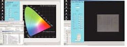
"After modules for each test are built in IMAQ Vision or FlexMotion," says Collier, "they can be called as standard test sequences from the TestStand program." These modules can include a number of functions; for example, modules developed within IMAQ Vision can include image capture, image analysis, and data display. These are then integrated into the LabView environment and called from the TestStand program (see Fig. 3).
features, advantanges, benefits

Costing from $200,000 to $270,000, the DisplayCheck MDT-250 system was debuted at the 2004 Society for Information Display Symposium, Seminar and Exhibition (May 23–28; Seattle, WA, USA; www.sid.org). The system is already being used to automate the characterization of LCOS microdisplays at a number of semiconductor locations, including Brillian, and at multiple locations in Taiwan.
"In developing the MDT-250," says Lewis Collier, president of DisplayCheck, "we understood that the operator would simply be required to load a part into the test fixture, enter the part-identification information, and start the test program. "At the same time," says Collier, "we realized that production engineers might need to evaluate the captured images and analyze features such as brightness, uniformity, contrast ratio and the microdisplays' response time in situ. Because of this, the MDT-250's interface includes a report window that provides these data in database-compatible format. These data can be used to analyze each device as it is produced and provide feedback to semiconductor-manufacturing engineers."
Company Info
Adimec, Eindhoven, The Netherlands www.adimec.com
Brillian, Tempe, AZ, USA www.brilliancorp.com
Danaher Motion, Salem, NH, USA www.neat.com
DisplayCheck, Exeter, RI, USA www.displaycheck.com
Hana Microdisplay Technologies, South Twinsburg, OH, USA www.hanaoh.com
Illumination Technologies, East Syracuse, NY, USA www.illuminationtech.com
Kopin, Taunton, MA, USA www.kopin.com
Microdisplay, San Pablo, CA, USA www.microdisplay.com
Moxtek, Orem, UT, USA www.moxtek.com
National Instruments, Austin, TX, USA www.ni.com
Navitar, Rochester, NY, USA www.navitar.com
Ocean Optics, Dunedin, FL, USA www.oceanoptics.com
Schneider Optics, Hauppauge, NY, USA www.schneideroptics.com
Thales Optem, Fairport, NY, USA www.thales-optem.com
Thor Labs, Newton, NJ, USA www.thorlabs.com
United States Display Consortium, San Jose, CA, USA www.usdc.org