Infrared cameras enhance machine-vision systems
By Greg Hollows
Engineers and system integrators are becoming increasingly familiar with the capabilities offered by IR technology, its unique system parameters, and the factors that have to be reviewed when selecting an IR machine-vision camera. In addition to common optical aspects of a machine-vision system such as the field of view and spatial resolution, IR systems have two unique parameters: thermal resolution and spectral range. Thermal resolution (or contrast) measures the ability to distinguish changes in temperature.
Another way of looking at contrast is through signal-to-noise ratio. Noise sources include heat generators and surrounding materials, optical components, housings, and human interference such as body-heat-raising temperature or air movement causing faster cooling. For example, an inspection station that monitors quality of injection-molded parts should differentiate between the area above an air bubble in a cooling plastic-molded part and the properly molded material around it. Contrast is one of the most important characteristics that determine the ability of an IR system to produce an image sufficient for the system to complete its job regardless of variances such as different colors of inspected parts, slight shifts in position, and unfavorable illumination conditions.
Spectral range is the band of wavelengths that the system can detect without saturation. The IR spectrum is commonly divided into three bands: near-infrared (NIR; 0.75 to 3 µm), mid-wavelength infrared (MWIR; 3 to 5 µm), and long-wavelength infrared (LWIR; 7.5 to 13.5 µm). Many IR vision sensors working in the NIR spectrum are made of indium gallium arsenide and cover the 0.9- to 1.7-µm range. MWIR sensors are made of indium antimonide and cover the 3- to 5-µm range. And LWIR sensors are based on quantum-well-microbolometer technology and cover the 7.3- to 13.5-µm range. Commercial systems usually fall into one of three categories of spatial resolution, which is a measure of a system’s ability to reproduce object detail: low (160 × 120 pixels), mid (320 × 240 pixels), and high (640 × 480 pixels).
ANALOG NIR CAMERAS
Near-IR cameras for machine vision can be based on CCD sensors. For example, measuring 44 × 44 × 87 mm and weighing 170 g, the Hitachi KP-F2A NIR camera features an increased sensitivity in the near-IR range that peaks at 760 nm and reaches 1200 nm. The camera is built around a 1/3-in. frame-transfer CCD with a high spatial resolution of 658 × 496 pixels. The analog video output is 1.0 V p-p, 75 Ω unbalanced available through a BNC connector.
This camera could be a good choice for material-analysis applications ranging from food-and-beverage processing to metal fabrication and finishing. It offers 30-frames/s progressive signal format and electronic shutter speed selectable from 1/60 up to 1/8000 s. The camera’s key parameter-wide spectral range-lets it detect product defects not easily recognized by visible-spectrum cameras.
For many applications, IR cameras bring the ability to properly recognize an object and its condition under difficult lighting conditions, such as reflective surfaces that produce high levels of visible-spectrum noise, excessive or extremely low levels of illumination, changing light intensity, and other factors. Near-IR cameras, in particular, are especially suited for inspecting material uniformity and material condition under the surface.
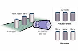
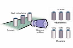
For example, a metal finishing line equipped with the KP-F2A camera in an inspection station can detect defective parts coming out of a painting, anodizing, or electroplating operation. When integrated with directional IR illumination, significant contrast between the untreated matte surface and the finished glossy surface becomes easily apparent (see Fig. 1). A simple image-processing algorithm can be used to quickly and repeatably determine whether the parts meet the required specifications. Likewise, when the color of the bare part and the color of the finish are almost identical, visual inspection alone cannot reveal poor finish quality and bare spots. Near-IR machine vision, however, can identify the trouble areas, making for a useful production or quality-assurance tool.
FPA CAMERAS
A thermal camera’s wavelength determines the range of temperatures it can register. When used for thermal imaging, thermography, and temperature analysis, the most important parameter is a camera’s thermal resolution (or sensitivity) within the range. Thermal resolution characterizes a camera’s ability to distinguish small temperature changes.
For example, the EO ThermoVision A20 thermal camera from Edmund Industrial Optics has high thermal sensitivity of 0.12°C at 30°C at 50/60 Hz. Based on technology from FLIR Systems, the camera is designed around a focal-plane array, uncooled microbolometer. The spectral range spans 7.5 to 13 µm, and the spatial resolution is 2.7 mrad. Three lenses (12°, 25°, and 45°) are available. Users have a choice of analog composite output only on the basic A20V model, or a combination of analog composite and digital FireWire I/O on more advanced models. The composite formats include RS-170/NTSC or CCIR/PAL, and the digital FireWire formats are IEEE-1394 8/16-bit monochrome and 8-bit color.
A typical process-control or inspection machine-vision system includes a camera housing, an image sensor, and a lens for focusing the desired area of the object onto the active area of the sensor. It also includes a camera/computer interface, a computer for processing the image data, a display, a machine interface to control the actuators based on the processed data, and software to run the whole system. The majority of machine-vision systems use image-analysis software to process the received image and display the image for the operator to interpret, or make a decision based on a certain algorithm.
Semiconductor manufacturing-particularly wafer testing-and electronic product assembly lines have experienced the highest growth of machine-vision system applications. Now, assembly lines producing printed-circuit boards for the consumer-electronics industry also are beginning to see the benefits of IR vision technology. Traditional visible spectrum and x-ray inspection stations can detect a missing component or poor solder joint and identify relatively large cracks and broken traces. However, they cannot predict whether the assembly will function properly when powered, and visible spectrum systems cannot find defects that are not visible at the surface.
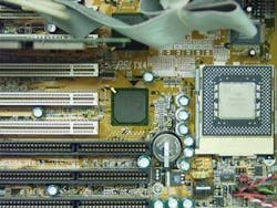
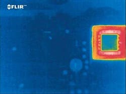
In addition to performing traditional tests, an IR machine-vision inspection station equipped with an IR camera can analyze a temperature map of a powered board (see Fig. 2). It finds numerous defects such as microscopic shorts hidden under the solder resist and excessively hot components. These anomalies indicate a defective or incorrectly installed component or signal exceeding normal operating levels.
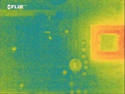
For example, an aluminum electrolytic capacitor installed with reversed polarity generates heat and is spotted by the station. The system also finds parts of the circuit that run too cold, which indicates that the power is too low or not applied. For instance, a rectifier diode installed in reverse stops current flow downstream, keeps the temperature of that part of the circuit below normal operating levels, and changes the thermal signature.
The range of applications using IR machine-vision systems is constantly growing. The technology allows manufacturers to substantially increase the quality of their products and minimize waste by quickly pinpointing defects and their causes.
GREG HOLLOWS is product line manager, Edmund Industrial Optics, Barrington, NJ, USA; www.edmundoptics.com
Company Info
Edmund Industrial Optics, Barrington, NJ, USA www.edmundoptics.com
FLIR Systems, Boston, MA, USA www.flirthermography.com
Hitachi Denshi America, Woodbury, NY, USA