Introduction to Polarized Cameras
Stefan Waizmann, Technical Marketing Engineer, SVS-Vistek
Along with intensity, propagation direction, frequency, or wavelength spectrum, polarization is one of the basic properties of light. In machine vision, polarization cameras are used to capture polarization image data, which cannot be detected by conventional imaging devices. In doing so, these cameras have opened the door to novel applications in industrial and scientific applications and beyond. Prominent examples include analyzing carbon fiber orientation, visualizing tensions in glass caused by stress-induced birefringence, reducing reflections and glare, or simply enhancing the contrast between materials that are difficult to tell apart with conventional imaging modalities.
What is Light Polarization?
Machine vision applications often rely on automatically analyzing digital images. The images themselves contain information on the interaction of light with the materials of interest. The type of information captured in the images depends on the image acquisition technology employed. A digital monochrome or color camera in combination with adequate optics is most commonly used in industrial machine vision. The cameras capture the intensity distribution and, in case of the color camera, additional information on the wavelength of the reflected or transmitted light of the objects of interest.
Light carries additional information that can be used to probe target objects. The light’s electromagnetic waves are characterized by their intensity, wavelength, phase, and polarization. With polarization cameras, information on the spatial distribution of the polarization state of light can be captured.
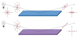
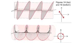
Polarization is a property that characterizes the geometrical orientation of the oscillation of the electric field of light. Linear polarized light, for example, is light that oscillates only in one plane perpendicular to the direction of propagation. Graphic A visualizes a linearly polarized wave of one wavelength. Additionally, the figure shows circular polarization.
Linear polarized light can be thought of as the addition of two coherent waves along two orthogonal directions. An optical active media can show a different refractive index for polarization along these two directions such that the two partial waves propagate with different speeds through the media and acquire a phase difference. Adding these two phase-shifted waves results in elliptical or circular polarization, as the resulting electric field vector turns in an elliptic or circular pattern (Graphic B). Circular polarization is obtained for a phase shift of exactly ±90°.
Measuring the Polarization
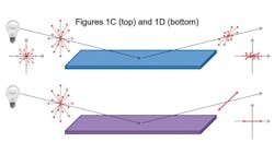
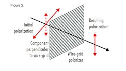
Linear polarizers can be used to characterize the light polarization. It is an easy and efficient way to obtain linear polarization from unpolarized light. Multiple realizations of polarizers exist and explaining them all would surpass the scope of this article. Here we want to focus on the grid polarizer. This is an optical element consisting of an array of subwavelength parallel metal nanowires. The component of the incident electric field that is polarized parallel to these metal wires is blocked in a way that only the polarization component perpendicular to the nanowire grid is transmitted. These nanowire grids are employed in some polarized cameras.
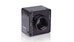
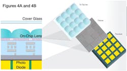
For example, think about, a camera using the 5 MPixel IMX250MZR Sony sensor. The Sony sensor is based on the 2448 × 2049 pixel, 2/3” IMX250 CMOS sensor with 3.45 μm pixel size. A four-directional polarization square filter array is overlaid directly on top of the pixel array and beneath the micro lenses. This filter consists of repeated 2×2 patterns consisting of grid polarizers with four different angles at 0°, 45°, 135°, and 90°. Each polarizer filters the incoming light so that only the polarization components perpendicular to the grid orientation can pass through and be detected by the underlying photodiode. Thus, a four directional polarization image can be captured in one shot.
In subsequent post processing, the 5 MPixel image can be used to obtain four size-reduced images (1.25 MPixels) filtered by one polarization filter, respectively. Additionally, the images can be used to estimate the spatial distribution of the brightness of the average of each 2x2 pattern, as well as the associated linear polarization angle and the DoLP.
The pixel intensities of a 2×2 pattern are a measure of the amount of light with 90° (I90), 135° (I135), 45° (I45), and 0° (I0) polarization, respectively. Addition and subtraction of these intensities are known as Stokes Parameters. Note that the fourth Stokes parameter S3 = IR – IL, which is calculated from the intensities of right and left circular polarized light, cannot be obtained from the image.
S0=I0 + I90
S1=I0 – I90
S2=I45 – I135
Conveniently, the polarization angle and the DoLPare easily computed from the Stokes parameters. The inverse tangent needs to be computed such that it returns values in the closed interval [-180°,180°].
Examining these values provides imaging contrast enhancements in a multitude of applications compared with standard camera imaging. Also, note that the degree of linear polarization does not quantify the amount of circular polarized light. Perfectly circular polarized light will have a value of DoLP = 0. Nevertheless, many applications do not require estimating the circular polarization.
Polarization Application Examples
Calculating the spatial distribution of the polarization angle as well as the DoLP increases the information content of the measurement.
Many applications exist for such measurements—for example, analyzing the orientation of carbon fibers, visualizing tensions in glass caused by stress induced birefringence, reducing reflections and glare, or enhancing contrast between similar materials that are difficult to tell apart with conventional imaging methods.
Some application examples are shown.
Plastics, glass, metals, and liquids display intrinsic polarization properties that result in unwanted glare and other artifacts using traditional imaging. Polarization cameras use polarization properties to visualize defects such as stress and scratches, while reducing glare, improving edge detection, and enhancing contrast. By filtering light, polarization cameras will improve a machine vision system’s capture, especially when inspecting objects that would otherwise be very difficult to identify in applications as diverse as semiconductors, consumer electronics, flat panel displays, packaging, and microscopy.
