Automated industrial controls and data acquisition converge in a programmable automation controller for packing beverage mixes.
By C. G. Masi, Contributing Editor
Once entirely separate spheres of technology, data acquisition (DAQ) and programmable automation have been on a collision course for decades. From a modern applied-technology perspective, DAQ systems and automation controllers clearly form two complementary parts of an important industrial automation whole: real-world sensory input and real-world machine control. The whole is sophisticated industrial process control using programmable automation controllers (PACs).
Innoventor Solutions built a system for a major beverage company that shows just what PAC systems can look like. The beverage manufacturer had been progressively automating its process for some time and asked Innoventor to automate what had previously been a manual-labor-intensive step in the packaging line.
The product is a cylinder containing a stack of individual packets of dry mix used to make single beverage servings. These cylinders are approximately 2 in. (5 cm) in diameter by 5 in. (12.7 cm) high. The cylinders have nonmetallic sides with ferrous-metal caps at their tops and bottoms. The bottom is permanently attached to the cylinder wall, but the top can be removed and replaced. The containers also have a safety seal around the top that a consumer removes when first opening the cylinder.
PACKAGING PROBLEM
The overall packaging line’s construction limited the number of products that might be on the line at any time to no more than five. The engineers settled on the barcode printed around the label’s bottom as the most useful identifying mark common to all labels. Every label of every package must have a barcode for the semi-automated checkout lines at retail stores. The barcode must uniquely identify the product for inventory control, as well as for pricing purposes, so it incidentally identifies the label. The sealer can use the leading bar in the barcode to determine the orientation necessary to make the seal wings avoid the label graphics. The system then uses the barcode information to determine into which of five output chutes to sort each cylinder for final packing into cases for shipping.
A handler picks up a cylinder to be sealed from a conveyor and places it on a spindle. Then, three cameras, spaced 120° apart around the cylinder’s axis, take one image frame each. Each image has a field of view (FOV) approximately 70° wide and high enough to view the barcode, which is always placed at the bottom of the label. The barcode, if it were centered in the FOV, would subtend 43°. “I can read any barcode within 60°," says Sam Hammond, chief engineer at Innoventor. "If it gets beyond 60°, focus and the parallax effects start making the lines disappear.”
The vision system has two tasks: to read the barcode and to find the leading edge of the leading bar. Reading the barcode identifies the product and, therefore, the label graphics. The leading edge is information that orients the cylinder label with respect to the machine. The system uses a look-up table to find the angular displacement from the barcode leading edge needed to properly orient the seal. Adding the offset and the displacement gives the required rotation.
“I have a better-than 50/50 probability of seeing [the barcode] the first time,” Hammond says. “If I don’t see it in any of the first three images, I rotate 60° and then I look again. I can always see it the second time. I may still [have to] center it again, because my validity check on the read might not be high enough."
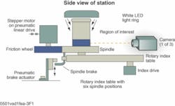
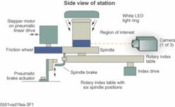
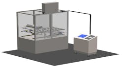
Clearly, even illumination is needed completely around the base of the cylinder. That calls for a ringlight. A ringlight located above the cylinder will produce an illumination pattern that will be bright near the cylinder's top-where it is not needed-and relatively dim near the bottom where it is. Placing a ringlight around the cylinder's base, however, would make for a mechanical nightmare, since cylinders move into and out of position on six spindles that move from station to station atop an indexing table (see Fig. 1).
The solution is to place the ring illuminator overhead to clear the cylinder's tops as they move into position. To get enough evenly distributed light around the base, Innoventor's designers mounted a flat white annulus around each spindle. The annuli move with the spindles, and, when a given spindle is at the vision station, its annulus diffusely reflects light coming down from the ringlight over the cylinder, providing even illumination for the camera's FOVs.
The indexing table is a circular plate 23 in. (58 cm) in diameter mounted on a Model 601RDM6H24-270 indexing table from Camco-Ferguson. A robot arm picks cylinders from one conveyor and places them on the spindle at the first position, where a magnet at the spindle's center locks it in place in a chamfered well. The chamfer forces the cylinder axis to line up with the spindle rotation axis despite some misalignment between the robot arm and the spindle.
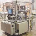
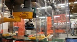
The table then indexes to bring that spindle into the second position, where the vision system finds the barcode, reads it, and measures the angular offset. This second station has a spindle motor that comes in to turn the cylinder to the correct orientation. Each spindle has a brake that the system sets to keep the cylinder oriented correctly as it travels to the next position, where the sealer applies the seal. Finally, at the fourth position, another robot arm lifts the cylinder off the spindle and places it onto a second conveyor (see Fig. 2).
Up to five different products can be coming down the input conveyor line. They arrive in no particular order, so the vision system tells a sorter, which is the next machine in line, which product type each cylinder should be sorted to. A gate closes off each sorter exit chute. As the cylinder approaches a gate, it trips a SICK Model WE1000 electric eye that signals the sorter to ask: "Is this mine?" If the answer is "yes," the sorter swings the gate to guide the cylinder off the conveyor and into the chute. If the answer is "no," the gate stays closed and the cylinder goes on to the next chute.
System Setup
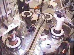
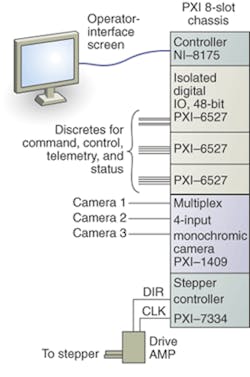
The hardware consists of a number of PCI Extension for Instrumentation (PXI) modules slotted into a NI PXI-1000B 8-slot PXI chassis from National Instruments (NI; see Fig. 3). Modeled roughly on the architecture of the VXI (VME Extension for Instrumentation) platform that has been used for automated test equipment since the late 1980s, PXI includes a mainframe, or chassis, that holds a number of instrumentation modules. The most essential module is the controller, which may be an embedded host computer or a link to an external host. Other modules are specialized electronic instruments from any of 68 vendors (members of the PXI Systems Alliance) who provide everything from general-purpose DMM modules to specialized microwave test-instrument modules.
In this case, the PXI chassis contains six modules. The controller is an NI 8175, which incorporates an 866-MHz Pentium III microprocessor running Windows 2000. Next are three NI PXI 6527 isolated digital input modules, each one providing 24 input and 24 output channels capable of handling 24-V level signals for driving relays. The next module is an NI PXI 1409 multiplexed monochrome camera input module capable of collecting images from up to four cameras. The final module is the NI PXI 7334 stepper-motor controller.
The cameras are all Cohu Model 2622-2000 monochrome units with RS-170A output, operating at 30 frames/s with 768 x 494-pixel resolution through a 1/2-in. interline-transfer CCD. The lenses are 16-mm fixed-focus units from Edmund Industrial Optics. To get the optical properties that the application requires (FOV, magnification, and depth of field), Hammond's team fabricated spacers to increase the lens'; object distance. The system provides a three-pixel width for the narrowest barcode lines.
The LED ringlight is an Advanced Illumination Model RL4260-WHIM24. "There is a little bit of a trick there," Hammond says. "You need a white surface at the base giving a diffuse secondary scatter to image the shinier label types. To get the right reflectors, we cut them out of CD labels and replace them about every six months."
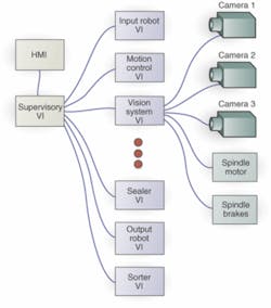
Hammond's group wrote the entire project in NIs LabVIEW test-programming environment. One of that environment's advantages is the ability to divide the software up into any number of sections (that is, virtual instruments, or VIs) that run simultaneously (see Fig. 4). " Now, we all know they're really time-slicing," Hammond points out," but if I've got a good, fast machine, and the process is slow compared to how fast the machine is, it seems like everything is running in parallel." The entire system runs under an overall supervisory VI. Each sub-VI controls the activities at one of the stations.
Each sub-VI communicates with the hardware elements it needs individually. For example, the vision system at Station 2 controls the three cameras, as well as the spindle motor. It also sends a signal to lock the spindle brake. This makes it possible to run all the processes, represented by the sub-VIs, independently in a multithreaded environment. The different processes coordinate by passing parameters through the supervisory VI.
Having different processes running under independent code elements makes developing and maintaining the system much easier. To upgrade the software for one process, for example, software engineers need only to deal with one code element. Everything else is unaffected unless the change has a direct effect on the information that process passes to other processes. The architecture is especially useful in a collaborative-engineering environment. Separate individuals or small groups can work on different processes independently.Features, advantages, benefits
“What our machine has to do,” says Sam Hammond, Innoventor Solutions chief engineer, “is to identify the right orientation based on the label type for a seal that goes across the top and has wings that press down the side.” The challenge was complicated by the fact that the wings have to be oriented correctly to avoid obscuring the label graphics. A further complication was that there were some 250 possible label graphics; each could be changed at any time.
“It sounds very simple,” Hammond points out, “but the complexity is that these labels have every bit of artwork and color that you can think of. There are very soft textures, shiny textures, some metallized portions, and different color schemes and patterns.”
Company Info
Advanced Illumination, Rochester, VT, USAwww.advancedillumination.com
Camco-Ferguson, Wheeling, IL, USAwww.camcoindex.com
Cohu Electronics Division,
San Diego, CA, USAwww.cohu.com
Edmund Industrial Optics,
Barrington, NJ, USAwww.edmundoptics.com
Innoventor Solutions, Maryland Heights, MO, USAwww.innoventor.net
National Instruments,
Austin, TX, USAwww.ni.com
PXI Systems Alliance,
San Diego, CA, USAwww.pxisa.org
SICK,
Minneapolis, MN, USA www.sickusa.com
