Choosing the correct type of lighting is of prime importance when developing machine-vision applications.
By J. Marcel Laflamme and Greg Dwyer
Human vision is an extremely complex phenomenon and has yet to be duplicated in machine-vision systems. While machine-vision systems use CCD (or CMOS) based cameras to image areas of a scene, the cameras do not “see” the object presented to them-they only measure the light that an object reflects to them. The goal of machine-vision lighting is to consistently allow a machine-vision system to measure the energy reflected from objects. The camera will not change, and the object is not supposed to change, but if the light reflected from the observed object changes, the camera will record a different image.
In designing machine-vision systems, developers must create as much of a difference in contrast as possible between the area of interest of an object and the areas of no concern. Because the angle of incidence of light equals the angle of reflection, a ray of light from a light source reaching a flat surface will reflect in the exact opposite angle. As the light ray reaches the camera, an image of the part is captured. However, if the object is tilted while leaving the light source and camera is in the same position, the ray of light passes beyond the camera, and the image of the part will fail to be captured.
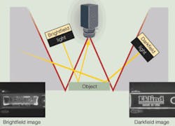
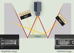
On an object with a perfectly flat, smooth mirror surface, all light sources originating from outside the legs of the W will not be reflected back to the camera (see Fig. 1). The surface of the object will be dark to the camera, hence the term darkfield illumination. All sources of light originating within the legs of the W will be reflected to the sensor, hence brightfield illumination. In darkfield lighting, any break in the surface of the object will change the direction of the light ray, and a bright area will be reflected to the camera. In a brightfield lighting configuration, a break of the surface will reflect light away from the CCD and appear dark.
VARYING WAVELENGTHS
Another important component of lighting is its wavelength. White light consists of many wavelengths, and when it comes into contact with an object some of it will be reflected and some absorbed. As the properties of the object will determine which wavelengths will be reflected and absorbed, the wavelength or color of the light source determines which wavelengths are reflected and which are absorbed. Using a color wheel as a guide, the proper selection of light-source colors can be selected to create contrast between features of an object.
On the color wheel, the color that most closely matches the feature of interest of the object is selected. To make that object feature appear darker to the camera, a light source of the opposing color is chosen. To make that object feature appear brighter, a light source of the same color must be selected.
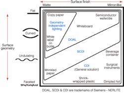
More complex lighting designs are often needed to accommodate highly reflective (specular) or highly diffuse surfaces, gently curved or faceted surfaces, and/or spherical objects. Many objects fall between the scales representing the surface characteristics of increasing geometric complexity and of increasing specularity, and the lighting used must provide high contrast between features of interest, such as surface abnormalities or identification characters or codes and their backgrounds (see Fig. 2).
For example, when an application involves a flat (planar) or gently curved surface that is highly specular, a diffuse on-axis light (DOAL) should be considered. With the diffuse on-axis lighting technique, light rays reflect off a beamsplitter and onto an object at nearly 90°. The rays travel along the axis created between the camera and the object.
With this coaxial lighting approach, specular surfaces perpendicular to the camera reflect directly back to the camera and appear bright, while surfaces at an angle to the camera reflect light away from the camera and appear dark (see Fig. 3). Light-absorbing (nonspecular) surface areas will also appear dark. However, lighting techniques that involve beam-splitter technology reduce the light intensity reaching the camera as there are losses incurred as the light source crosses the beamsplitter. Application testing is advised.
SPECULAR OBJECTS
For specular objects with moderately curved or undulating surfaces, the technique of continuous diffuse illumination provides a greater solid angle of illumination. This “solid angle of illumination” refers to the size of the angle created at the theoretical point of convergence of light rays in reference to the width of their origin at the light source. The greater the solid angle of illumination, the greater the light’s capacity to uniformly illuminate curved, undulating, or faceted surfaces. Lights with a very large solid angle of illumination can make very irregular backgrounds appear quite smooth.
Using a square continuous diffuse illuminator (SCDI) effectively “fills in” and brightens small to moderate size bumps and depressions that the DOAL technique (with a lesser solid angle of illumination) would present as dark areas to the camera. This technique provides excellent contrast between slightly bumpy solder pads and the circuit board on which they reside (see Fig. 4).
SCDIs use a single light source with a slightly angled diffuser and slightly curved beamsplitter to provide a larger solid angle of illumination compared to a DOAL. But at the extremes of surface geometry and specularity, the SCDI technique must be taken to the next level to deliver very high uniformity of lighting from a very large solid angle of illumination. The CDI is a patented design using two independently controllable lighting axes. An illuminated precision integrating sphere is combined with an on-axis light source to yield a self-contained continuous diffuse lighting environment.
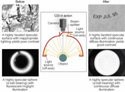
A CDI can uniformly illuminate up to 180° of a spherical object (see Fig. 5). The print on wrinkled foil illustrates how the large solid angle of illumination reaches into every angle created by the wrinkles and reflects brightly back to the camera. With this technique, only light-absorbing features such as the black print on the foil will appear dark to the camera. A CDI also can be used in applications involving objects inside clear packaging, such as blister-packed pharmaceuticals, by eliminating reflections from the clear cell coverings, making them virtually disappear while at the same time providing a high contrast view of the cell contents.
DIFFERENT PRODUCTS
Because objects to be inspected range in size and possess different physical attributes, lighting products must be available in a variety of sizes and incorporate wavelengths from UV to near-IR. In addition, the location and the availability of real estate and power at the inspection site will dictate the choice of lighting. These products can range from those that function in harsh environments where the presence of heat, moisture, and airborne contaminants must be countered, to those that fit in tight spaces and run from available system power, to those that deliver contrast-producing light trajectories from less-than-ideal locations within the system. In many cases, products that use diffuse lighting must enhance illumination uniformity across a field of view. Other applications demand lighting products that focus light intensely on a small target area from a given distance.
With the decreasing costs of smart-camera-based systems, vision applications are now much more affordable, and the number of currently deployed industrial applications has increased dramatically. Unfortunately, the cost of components that make up lighting products has not followed the same downward trend. Ten years ago, a $1000 light was a “bump on the log” of the price of a $20,000+ vision system. Today, the cost of the vision system is lower but the cost of lighting remains nearly unchanged. For while a single vision system can inspect many different products, each product may demand a unique lighting configuration. The challenge for lighting companies will be to embrace the newest technologies, to design more flexible and functional products, and to distribute them in the most cost-effective manner.
J. MARCEL LAFLAMME is business manager and GREG DWYER is in marketing at Siements Energy & Automation, Nerlite Division, Weare, NH, USA; www.nerlite.com.
