Andrew Wilson, Editor, [email protected]
In the manufacture of electronic connectors for the automotive industry, multiple metal pins are fused into plastic housings using many production steps. To ensure the correct placement of the connector pins within these housings, companies such as Tyco International (Princeton, NJ, USA; www.tycoelectronics.com/automotive) often use machine-vision systems to check the final product before it is packed and shipped.
“Often,” says Bradley Weber, director of international application engineering at PPT Vision (Eden Prairie, MN, USA; www.pptvision.com), these connectors are manufactured in a variety of shapes and sizes. The awkward dimensions can prove challenging when these parts must be automatically inspected.” At Vision 2005 (Stuttgart, Germany; November 2005), PPT showed a system for inspecting embedded pins within molded connectors that measured 6 × 1.5 in.
“One of the challenges of cost-effectively inspecting such parts,” says Weber, “is that the entire image must be captured before any image analysis can be performed.” This could be accomplished using a very-large-format camera or multiple cameras. Additionally, as the part moves along the conveyor, a linescan camera could digitize the entire image. “These options are expensive, due to the cost of large-format imagers, multiple cameras, and linescan cameras,” he says.
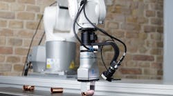
At Vision 2005, PPT offered a different approach to this problem using the company’s PPT 5200 area-array camera coupled to a C Series Impact Image processor. Parts are placed onto a stepper-motor-driven conveyor from IAI America (Torrance, CA, USA; www.intelligentactuator.com). “Using the built-in optical encoder of the stepper motor controller,” says Weber, the camera can be precisely triggered to capture multiple images of the part as it moves under the field of view (FOV) of the camera. A red FPH-100 ringlight from CCS America (Waltham, MA, USA; www.ccsamerica.com) mounted on the camera illuminates the parts.

As parts move along the conveyor, the PPT 5200 camera mounted with a 35-mm lens from Edmund Industrial Optics (Barrington, NJ, USA; www.edmundoptics.com) is triggered to take six 640 × 480 × 8-bit sequential images of the part. Captured images are transferred to the Impact Image Processor. Using the company’s Inspection Builder software, the images are stitched together using gray-scale normalized correlation.
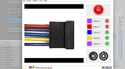
“The algorithm we have developed analyzes the overlap between the right-hand side (RHS) of the first image and the left-hand side (LHS) of the second image,” says Weber. “This process is then repeated with the RHS of the second image and the LHS of the third image and the other images in the sequence. By performing a normalized correlation between the overlap of these sequential images, the system reconstructs the entire 6 × 1.5 in. image of the connector. Both the series of sequential images and the stitched image can then be displayed using the Control Panel Manager (CPM), which is part of PPT’s Inspection Builder software.
After images are captured, processed, and displayed, the developer can use a number of image tools within the Inspection Builder software to make measurements of the part. “For example,” says Weber, “line-measurement tools can compute the distance between sequential pins that are 2.5 mm apart or between pins located across the entire 6-in. length of the connector.
While performing these inspections may take milliseconds, the process of stitching six sequential images takes about 1 s. “In a production-line environment, where it takes 3 s to move the part over the FOV of the camera, this is quite acceptable,” says Weber. Once measurement parameters have been set, they can be hidden from the operator using the CPM, an HMI package that contains graphical controls, data controls, and recipe management software. “In this way, the operator is presented with an easy-to-use GUI without the need to understand the underlying image-processing or machine-control functions,” says Weber.