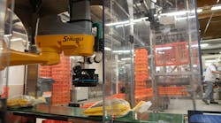
Real-time statistical process control ensures pharmaceutical-packaging integrity.
By C. G. Masi, Contributing Editor
When a US manufacturer of pharmaceutical packaging tubes wanted to upgrade its package-inspection system, it asked production-system integrator Averna Technologies for a solution that not only passively monitored tube quality, but actively fed the results back to process engineers and technicians using real-time statistical process control (SPC). “It’s a quality-monitoring system at a high level,” says Shahzad Sarwar, Averna director of industrial and real-time solutions, “inspecting dimensions, print quality, and other product attributes. The system includes visual inspection as well as nonvisual quality inspection for qualities such as wall strength and other mechanical characteristics.”
Warnings from the real-time SPC analysis system enable process technicians to catch and reverse adverse trends before the process starts making unusable tubes. Real-time SPC uses rapid sampling and running averages analyzed by software to predict when secular variations will build up enough to push the process into making scrap. It can call for adjustments soon enough to keep the process under control without burdening the line with excessive and unproductive maintenance calls.
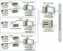
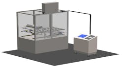
Averna developed a system that replaces the manual inspection station at the end of the production line (see Fig. 1). “Product-dimension variation was one of the challenges,” Sarwar recalls. The line fabricates a variety of containers that vary in diameter from 0.5 to 1.5 in. and in length from 3 to 8 in; they are used for a variety of products, from lipstick to toothpaste. All are metallic-made from thin roll-formed sheet stock a few tens of mils thick.
Each package has its own labeling, which must be inspected for placement, color, and print quality. The system must handle background finishes from shiny metallic to solid colors matched to the contents color. Printing can vary from essentially blank for lipstick cases to complex fine-print label warnings. In all cases, colors have to match standards exactly, printing has to be clear and unsmudged, and all graphic elements have to be oriented exactly with respect to position along the tube and orientation with the tube’s long axis.
System Architecture
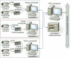
There are three in-line inspection stations and one off-line station. Each in-line station has its own host computer running image-acquisition and analysis software built with National Instruments LabVIEW and IMAQ design environments. The three hosts feed results to a fourth computer running Averna’s Proligent real-time SPC application.
The fourth computer also runs the data-acquisition application supervising the off-line station that makes nonvision measurements. It monitors such mechanical parameters as tube weight, wall thickness, and any additional parameters needed for a particular product.
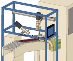
As tubes reach the first inspection substation, a proximity switch triggers image acquisition by two JAI Pulnix CV-M4CL+ cameras (see Fig. 2). These cameras inspect the visible parts of each tube. That is, the top camera views the uppermost side, and the side camera views one end. The cameras carry Schneider Optics Xenoplan 1:5 telecentric lenses to ensure accurate distortion-free dimensional measurements. Each camera also has an Advanced Illumination LED ringlight to provide consistent lighting.
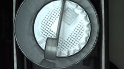
The station uses two StockerYale Lasiris SNF line lasers to project structured light patterns over the tube under inspection. The image-analysis software uses these patterns to ensure that the tube caps are on straight and tight (see Fig. 3).
The cameras use Camera Link to send images to a National Instruments PCI-1428 frame grabber. The frame grabbers reside in PCI expansion slots in the substation’s host computer, which are Dell desktop models with 3-GHz Pentium 4 processors running Windows XP.
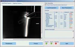
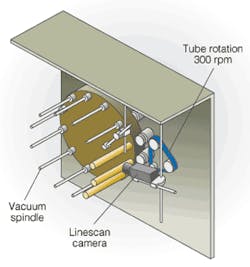
A second substation performs the print and finish inspections of the tube sidewalls (see Fig. 4). A vacuum sucks each tube off the conveyor onto one of the spindles of a Ferris-wheel-like rotating carousel. Each spindle has an alignment spacer on its side to make sure the tube sits square to the camera’s optical axis and a vacuum seal to ensure that it slides all the way down to a stop that locates it crosswise to the camera. As each spindle approaches the inspection camera’s field of view, a sheave attached to its end contacts a drive belt. The drive belt constantly rotates fast enough to drive the spindle at 300 rpm.
The belt is set up to contact two spindles at once. Upon initial contact, the spindle spins up from 0 to 300 rpm. By the time it reaches the camera, its speed is constant. After passing the camera, the spindle’s sheave leaves the drive belt and spins down again to zero. Finally, another vacuum tweezer moves it from the carousel back onto the conveyor.
This station has a Dalsa Trillium TR-37 linescan camera whose scan line parallels the spindle axis. A LL6212 laser line light manufactured by Advanced Illumination provides even illumination along the scan line. This camera uses low-voltage digital signals to send images over a real-time system integration bus to a National Instruments PCI-1424 frame grabber in another Dell desktop computer.
The camera’s scan line traces out the entire tube sidewall surface as the tube rotates. The host computer then assembles the scan lines into a flat image. In effect, the system unrolls the entire tube sidewall into one flat image covering the whole surface. The software looks for correct labeling, color values and registration, print quality, and label positioning.
The final station has the same construction as the first station, but it looks at the tube from the other side and the other end. Again, it makes dimensional and geometrical measurements, which it passes along to the SPC computer.
The SPC computer collects data on each tube from the three substation hosts and combines it with nonvision data from the off-line samples. Averna Proligent SPC software written in C# then statistically analyzes those data to determine random and secular process variability and look for adverse trends. This computer also packages the information and uploads it to the enterprise-wide manufacturing execution system over the company’s intranet. Engineers and managers throughout the company can then query the Proligent SPC application for reports of current operating conditions and compare them to historical archives.
The Final Analysis
“There were several challenges in this application,” says Sarwar, “such as adjusting the inspection system to different tubes and interfacing the system to the existing production line.” Operating in an industrial environment also presented challenges. The manufacturer had to deploy high-end machine-vision cameras, lighting components, interface devices, and standard desktop computers in a production environment where the temperatures can become quite high.
In addition, the company needed to integrate data from several sources, including multiple automated vision systems and nonvision measurement tools. Averna’s Proligent software suite, which is designed to work in just this type of environment, eased the task. “The completed system,” Sarwar points out, “shows how useful a tool that integrates vision and SPC can be for maintaining production quality. It allows you to understand your process, find your bottlenecks, and ultimately improve the process.”
Company Info
Advanced Illumination
Rochester, VT, USA
www.advancedillumination.com
Averna Technologies
Ottawa, ON, Canada
www.averna.com
Dalsa
Waterloo, ON, Canada
www.dalsa.com
Dell
Round Rock, TX, USA
www.dell.com
JAI Pulnix
San Jose, CA, USA
www.jaipulnix.com
National Instruments
Austin, TX, USA
www.ni.com
Schneider Optics
Hauppauge, NY, USA
www.schneideroptics.com
StockerYale
Salem, NH, USA
www.stockeryale.com
