Andrew Wilson, Editor, [email protected]
Component identification systems play an important role in aerospace and automotive plants where large numbers of components must be tracked from early inventory to final product assembly. At the Ford Motor Company (Detroit, MI, USA; www.ford.com), marking Data Matrix codes on machined parts is a requirement for third-party component suppliers. According to Frank Maslar, a technical specialist with Ford, all components must adhere to a minimum C grade of the Automotive Industry’s Action Group (Southfield, MI, USA; www.aiag.org) before they can be accepted.
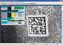
While pin stamping, laser etching, and inkjet printers can be used to form these 2-D codes, inkjet codes are too messy and hard to maintain in automotive environments. Although pin stamping is a low-cost, well-known procedure, laser etching is faster and can be beneficial in applications where codes need to be applied to rough surfaces. In these applications, laser-etching machines can create a clean-up pass before etching the code. This normalizes the background and makes the code easier to verify and read (see figure).
Says Maslar, “The key to achieving both successful verification and reading of 2-D Data Matrix code is achieving a successful contrast between the part’s surface and the code.” This is done through a combination of the correct resolution, lighting, and image-processing techniques. Because of surface irregularities that may be present on the part, the minimum cell size of these codes will differ for every surface condition. In general, the cell elements in the code must be larger than the surface irregularities. “For reading and verification,” says Maslar, “a good rule of thumb is that each cell element within the code must be resolved with between 8 and 12 camera pixels .
To achieve this, simple calculations can provide the field of view, code resolution, and focal length required, assuming other factors are known. For example, for a 20 × 20 code 12 mm square, a CCD camera of roughly 480 square pixels will have a 28.8-mm field of view with 10-pixel/cell resolution. If this camera is 300 mm away from the part, a 50-mm lens is required to achieve this resolution.
To read these parts requires more than determining the correct resolution. “Using red LED illumination with a red lens filter will mitigate the effects of different lighting characteristics,” says Maslar. Ford requires the quality of the codes to be verified immediately after they are marked. This will identify any problems with the marking process and provide feedback to suppliers for any preventative maintenance that may be required.
“In verifying such codes,” says Maslar, “it is best to avoid any image-processing techniques that could otherwise be used to enhance the contrast of the Data Matrix code.” In this way, a consistent grade can be given to each data matrix code. “Of course, when reading the part, image-processing techniques such as morphological operations do improve contrast and provide a more effective means of reading the code.”
For Maslar, smart cameras that provide both Data Matrix verification and reading capability often provide the optimal solution. However, these smart sensors do not provide the capability to visualize the image as it is being inspected. It is recommended that a PC be connected to each reading station so that the latest image can be displayed, allowing the operations personnel to observe the current conditions. Additionally, the smart cameras can store failed images, decoded strings, and performance data on the PC for later analysis.
Redundancy is also a major characteristic of robust systems. Rather than relying on a single reader tool, multiple reader tools can be programmed to decode one image. Each of these tools can be independently configured with different image processing algorithms to enhance the captured image. These different configurations can automatically compensate for part to part variations.
