Novel drives allow semiconductor-related positioning systems to be developed with very high accuracy and repeatability.
By Andrew Wilson, Editor
As semiconductor linewidths continue to shrink, manufacturers face the increasingly difficult task of accurately positioning and inspecting wafers. To do so requires positioning systems that maintain both high accuracy and repeatability over long travel distances. However, in many of these applications, traditional stepper and servomotors cannot be used. Instead, developers of precision motion applications and ultrafinely focused optical assemblies are turning to positioning systems based on the piezoelectric effect.
More than a century ago, Pierre and Jacques Curie noticed that applying an external force to a piezoelectric material resulted in positive and negative electrical charges appearing at the surface of the material. Similarly, applying a voltage to a piezoelectric material causes a deformation of the material proportional to the electric-field strength applied.
The two most commonly used materials in the construction of piezoelectric drives are lead zirconium titanate and lead magnesium niobate. These piezoelectric actuators are manufactured in stacks with electrodes arranged on both sides of a ceramic disk. Such polarized piezoelectric materials achieve repeatable nanometer and subnanometer-sized steps because, unlike traditional stepper and servomotors, they have no moving parts. Because of this, they require very little power and no maintenance and can be used to move relatively heavy loads. In addition, piezoelectric actuators and flexure-guided scanning systems can respond to motion commands in less than a millisecond and typically provide travel ranges of tens to hundreds of microns. For longer ranges piezomotor drives are available.
According to Stefan Vorndran, director of marketing communications at Physik Instrumente (PI), piezo linear motors can be divided into two groups (although this is somewhat of a misnomer)-“continuous” ultrasonic friction motors and “step” piezo walk motors. While both can, in principle, attain unlimited travel, friction motors generally feature higher speeds, while piezo walk motors are used in applications that demand higher resolution and force. In both design types, servo dither and the accompanying heat generation are eliminated because of the motors’ intrinsic steady-state autolocking capability. And, because both ultrasonic and piezo walk designs are nonmagnetic and vacuum-compatible, they are idea for applications in the semiconductor industry.
Due to their ferroelectric nature, piezoelectric materials exhibit hysteresis dependent on both the applied voltage and the previously traveled direction. For this reason, many manufacturers of piezoelectric devices offer closed-loop position feedback devices. Interestingly, the resolution (not to be confused with accuracy) of piezo actuators is better for open-loop than for closed-loop systems, because even the best servo and sensor electronics contribute to electronic system noise-the only piezo resolution-limiting factor. “In a servo-controlled piezo-based system, the sensor and control electronics are of considerable importance, and, with appropriate, high-quality systems, subnanometer resolution and stability are possible in closed-loop mode,” says Vorndran.
Continuous motion
Although piezoelectric friction and walk motors differ in their designs and are often patented, both use the piezoelectric effect to attain motion. Although the effect of both designs is continuous motion, the motors use different configurations of piezoelectric materials to attain this effect.
To demonstrate how such “continuous” motors operate, S-W. Ricky Lee and his colleagues in the department of mechanical engineering at Hong Kong University of Science and Technology have designed a rotary actuator by leveraging the twisting-extension coupling effect of a piezoelectric composite. To build a motor around this composite, an anisotropic piezoelectric composite laminate acts as a stator with an antisymmetric configuration (see Fig. 1). While one end of the stator is fixed, the other is placed in loose contact with a rotor disk. Once subjected to an electric field, the beam extends and twists in a motion resembling that of a screwdriver. The extension of the stator then brings one end into contact with the rotor. Due to mechanical friction, the rotor turns with the end of the stator. When the electric field decreases, the stator contracts and twists back.

Due to rotary inertia, the rotor will continue to rotate in the same direction. Eventually, the stator separates from the rotor, which continues to turn by rotary inertia. Repeating this process, a continuous rotary motion is achieved by applying a high-frequency cyclic voltage to the piezoelectric laminate. Although such motion is termed continuous, the means by which the motion is generated is a high-frequency step process.
“Because Moore’s Law compresses both IC linewidths and feature sizes,” says Harry Marth of PI, “nanopositioning mechanisms embedded in front-end production and metrology tools have difficulty keeping pace; they must provide 10X to 1000X higher precision than the feature size of the semiconductor. Because of this, vibrations, position errors, and drift need to be controlled to less than 0.1 nm. Unfortunately, conventional nanopositioning systems have high accuracy and short travel or do not provide the required stability and precision required.
To overcome these limitations, PI has developed its NEXLINE Series of piezoelectric nanopositioning systems especially for the semiconductor industry. Using a combination of shear and linear piezo actuators, the NEXLINE devices create linear motion by producing shear in the x direction with the linear actuators providing the clamping/unclamping motion in the z direction.
When a number of actuators are located linearly, the resultant effect is a linear motion in the x direction. Planar motion based on x/y shear motion is also feasible (see Fig. 2). To develop a rotary motor based on such designs requires the shear and linear actuators be placed in a stator/rotor configuration.

The ultrasonic friction motor concept has been used by Nanomotion in the design of its range of Nanomotion motors. Using simultaneous excitation of the longitudinal extension mode and the transverse bending mode creates a small elliptical trajectory of the ceramic edge, achieving a dual-mode standing wave. By coupling the ceramic edge to a precision stage, a resultant driving force is exerted on the stage, causing stage movement. The periodic nature of the driving force at frequencies much higher than the mechanical resonance of the stage allows continuous smooth motion for unlimited travel, while maintaining resolution and positioning accuracy. Travel can be linear or rotary, depending on the coupling mechanism.
Accurate and repeatable
When choosing a piezoelectric positioning system, the system integrator must first determine the maximum payload that the drive is required to handle and the minimum incremental motion or resolution required. This is the smallest distance the stage can move. Once determined, both the repeatability and accuracy of the stage must be determined. While positioning accuracy measures how closely the motion matches a specific command, repeatability measures the extent to which successive attempts to move to a specific location varies in position.
In the design of its NTS NanoDirect series, for example, DTI-NanoTech specifies a maximum vertical load of 3 kg, a maximum travel length of 100 mm, a unidirectional repeatability of less than 1 µm, and an accuracy of less than 0.03% of full scale. To control the drives, the company supplies its own DSP-based NanoDirect controller in either one-, two-, or three-channel configurations that can achieve an open-loop resolution of 1 nm and a maximum closed-loop resolution of 50 nm.

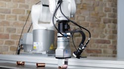
DTI-NanoTech combines three stages into an angular linear motorized nanopositioning system-RoboMate (see Fig. 3). The desktop-sized combined rotational and linear motorized nanopositioning system allows a camera or probe to be positioned at variable angles with respect to the object under test (see Vision Systems Design, June 2006, p. 15). “In semiconductor applications, the captured image is always fixed on a specific point on the die or wafer, while its angle of incidence can be varied,” says Valentin Zhelyaskov, vice president of DTI-NanoTech. “This allows images of die bonds to be viewed from different angles so that semiconductor manufacturers can check whether the bonds have a consistent shape.”
Linear and rotary
A number of companies offer both linear and rotary motors based on the piezoelectric effect. These are available as either linear or rotary motors embedded in x, y, and z positioning stages and can be supplied with their own or third-party feedback controllers and PC-based positioning software.
For precise positioning of optic components such as mirrors and laser diodes for adjustment and mounting in semiconductor technologies and electronics, for example, Piezosystem Jena offers its NanoX series of one-axis linear stages. With a linear motion up to 800 µm, the drive provides 1.2-nm resolution in a unit measuring 60 × 60 mm. For controlling the focus of micro objective lenses and object lenses, the company also has developed its MIPOS series, which attaches to standard threads on Zeiss, Leica, Nikon, and Olympus microscopes. These devices allow the piezo device to perform fine-focus adjustment of the objective lens of the microscope.
New Scale Technologies (NST) has also demonstrated a novel optical-zoom camera module using its patented Squiggle motor technology (see Vision Systems Design, April 2006, p. 24). The company’s first prototype uses a 2.4 × 2.4 × 6.5-mm linear motor to move a lens approximately 4 mm with better than 10-μm closed-loop repeatability.
The design of the Squiggle motor uses ultrasonic vibrations to produce linear movement without gears or other additional parts and has a threaded nut with mating screw. This nut is vibrated by piezoelectric ceramic actuators. In operation, the nut vibrates in a “hula hoop” motion at the mechanical resonant frequency. According to David Henderson, president and CEO of New Scale Technologies, the design is a motion subsystem that integrates a linear guide, preload springs, limit stops, and a position sensor. “Single-chip controllers are under development by ASIC vendors and will be available soon,” he says.
Motor controllers
While most piezoelectric devices require a highly specific servo controller, PI’s ultrasonic drives can be driven by a number of conventional servo controllers from companies such as Galil, National Instruments (NI), or DeltaTau, all of which provide special software options to control piezo-linear motors.
“Commercially available high-precision DAC converters are often used to control analog piezo controllers,” says PI’s Scott Jordan. “They often provide between 12- and 16-bit resolution, and most developers prefer to use cards from companies such as NI that offer 16 bits of resolution. Used with PI’s P-628 or P-625 PIHera flexure nanopositioning stages with 1000- and 500-µm travel, respectively, a resolution of just 15 or 8 nm can be achieved. A 12-bit card would provide only 0.23- and 0.12-µm resolution with these stages-coarser than many motorized stages provide! Although these DACs’ fast analog update rate allows them to generate smooth arbitrary waveforms, there is unused analog-output bandwidth in a typical nanopositioning setup.
This underutilized time-domain capacity is used in PI’s patented HyperBit technology to achieve additional bits of physical positioning resolution with no loss of system bandwidth, stability, or accuracy. By using high-frequency modulation of the least-significant bits of a DAC, the LSB can be dithered using pulsewidth modulation at a frequency where the system is unresponsive, acting like a flywheel to provide smooth, stable motion with far higher resolution than the DAC’s native resolution (see Fig. 4).

Implemented either in software or hardware, the software is available for license by OEM designers. Implementations now include HyperBit-enabled LabVIEW subVIs, a Windows DLL for programmers using C and HDL for designers using FPGAs. “Since the time-domain capability of the DAC would otherwise go unused, there is no impact on system bandwidth, responsiveness, or speed,” Jordan says.

null
Understanding piezo-based drive systems
Simple piezo actuators expand proportional to the voltage applied to the piezoelectric material and feature a travel range of approximately 0.1% of actuator length. They also can be used to produce high forces to thousands of pounds and feature submillisecond response, frictionless, subnanometer resolution, and travel ranges typically between 10 and 100 µm.
Flexure-guided, piezo-actuator-driven nanopositioning/scanning systems use frictionless flexures to provide extremely straight and flat motion. Multiaxis systems are also available that are ideal for imaging resolution enhancement or stabilization by dithering a lens in front of a CCD sensor, a feature extremely useful in scanning-optical-microscopy applications.
Motion of integrated piezo actuators can be amplified by internal flexure amplifiers. Typically these feature motion ranges up to 1000 µm and have a frictionless, fast response of between 1 and 10 ms with subnanometer resolution.
For simple and flexure-guided devices, motion is proportional to the dc output voltage of the servo controller.
Ultrasonic friction motors are based on high-frequency oscillation of a piezo plate (stator). Oscillation is transferred to a slide or rotor via friction. These devices have unlimited motion, high speed, and fast response. However, due to friction, resolution is limited to typically 50 nm. These devices can be used to generate low forces and move between 1 to 6 lb.
Squiggle motors are a special form of ultrasonic rotary/linear drive converting rotation in linear motion via a lead screw. Although these are very compact, their precision is limited by the lead screw.
Piezo walk motors basically have unlimited motion. They are based on accumulation of small steps and offer picometer resolution in high-speed dither mode (direct piezo actuation). They are compact, feature a fast response of less than 1 ms and high stiffness, can move 120 lb, and travel speeds of approximately 1 mm/s.
Rotary piezo motor/lead-screw combinations replace the stepper/servo rotary motor with an ultrasonic rotary motor. As with classical motors, precision is limited by the mechanical precision of the lead screw. Although rotary piezo motors are smaller and have a higher torque than servomotors, they are slower and have shorter lifetimes. - A.W.