Embedding a vision system onto a circuit board allows the integrity of backplane pins to be closely monitored.
By Andrew Wilson, Editor
At first glance, some machine-vision tasks seem next to impossible to accomplish. Such a task was presented to Doug Wilson, president of PVI Systems, by one of the world’s largest suppliers of information-storage and management systems.
To provide high-speed data access in its mainframe storage systems, multiple hot-swappable 9U-format-disk controllers support terabytes of storage for IBM and IBM-compatible mainframes. Residing on multiple proprietary backplanes, these boards incorporate very-high-density metric (VHDM) connectors to ensure the integrity of multiple high-speed data-transfer and control signals.
“Should a card fail in such a system,” says Wilson, “it must be removed and tested. If the board fails this test, it can be replaced while the system is running.” In some cases, however, the board that is removed is tested and performs correctly. In these cases, it is necessary to inspect the system’s backplane to check the alignment of the multiple pins within each VHDM connector. If any of these pins is out of alignment, the backplane may need to be repaired or replaced.
Measurement accuracy
“Before such drastic actions are taken, it is necessary to accurately measure the relative positions of the backplane pins to determine if a bent or missing pin is the cause of the system’s failure,” says Wilson. “Replacing the backplanes means that the system must be taken off-line, increasing downtime costs for the end user.”
In high-density enterprise disk systems, two backplanes, known as mid-planes, face back-to-back and house multiple 9U-disk controllers. Two different formats of boards reside in each backplane. While the first houses 360 × 340-mm boards, smaller 360 × 120-mm boards are used on the opposite side of the mid-plane. Each of these boards is connected through a proprietary high-speed backplane using VHDM connectors.

Manual inspection of the backplane, with other system boards installed, is difficult to do, at best, and subject to operator fatigue and human error. Add in the safety and personnel factors imposed by the need to perform the inspection while the system is live, and it becomes clear that manual inspection is not a viable solution. A vision system that can be positioned within 50 mm of the backplane, capture the relevant image data, and check the pins within specified tolerance limits is required to properly inspect each of these VHDM connectors.
Wilson and his colleagues investigated several alternative designs. He initially studied the use of borescopes to remotely move the images from the backplane to an off-board camera. “To properly image the pins at a distance of 340 mm from the backplane within a 20-mm gap using a borescope,” says Wilson “would have been an expensive task. In addition, while such products are expensive, they lack sufficient resolution to provide the required measurement accuracy.” What was required was an inexpensive automated machine-vision system that could be placed within this 20-mm slot to within 50 mm of each of the connectors to ensure accurate and repeatable measurements.
Embedded vision
To perform inspection of each backplane’s VHDM connectors, Wilson and his colleagues embedded a machine-vision system into an unpopulated passive 9U board. Should any board in the system fail, it is removed and tested. If the test proves negative, the passive 9U imaging card is inserted into the same slot to image the backplane. An imaging system located 50 mm from the backplane then scans the connectors and provides the system operator with a report describing the type of test performed, who performed it, what slot it was performed on, the tolerance limits, and pass/fail inspection data for each pin.
“Using this system,” says Wilson, “a technician can ensure that system failure is due to a problem with the backplane pins, before the system needs to be rebuilt. This provides the user with the knowledge that the backplane rather than a single board lies at the heart of the problem.”
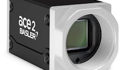
Three major components comprise the machine-vision system: the imaging board that includes a camera and motion system, a motion controller and I/O system, and a host PC. In the 360-mm-high backplane, connector pins with 2-mm spacing needed to be imaged across approximately 20 mm. To do this cost-effectively, a single STC-R640AS CCD lipstick camera head from Sentech was mounted within an unpopulated 9U board (see Fig. 1).

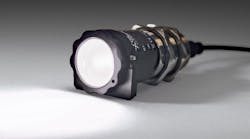
“From the initial design concept,” says Wilson, “we realized that darkfield illumination would be required to reveal any irregularities in the connector pin tips, without interference from other parts of the connector and housing. To accomplish this, two pairs of four LM2-AHR1-F1-N1 high-brightness red LEDs from Cotco International were mounted on a support bracket to illuminate the field of view of the camera. “The added advantage of this bracket,” says Wilson, “is that it can deliver power to the LEDs.”
Timing is everything
To image all of the connectors, the camera-and-light-source combination is moved across the 360-mm backplane of the system chassis. To do so required that the camera be mounted onto a small timing belt from W. M. Berg. A 15-mm stepper-motor controller with a built-in encoder from MicroMo Electronics is mounted in the plane of the board. Its motion is converted into rotational motion in the plane of the card using a miniature right-angle gearbox that reduces the speed of the stepper motor by 32:1 and a toothed gear that provides another 2:1 reduction. This final toothed gear attaches to the toothed timing belt and provides the means of controlling the linear motion of the camera.
“To compute the position of the camera as it moves along the timing belt,” says Will Schramm, project manager for the pin-inspection system and one of the cofounders of PVI Systems, “its exact position at the beginning and end of each scan must be known.” The 9U imaging board features two optical limit switches located at the beginning and end of the front of the timing belt. “As mechanical tabs mounted on the camera move through these limit switches, the camera is stopped automatically and thus both the initial and final positions of the camera can be computed,” Schramm says.
Once a preliminary design concept was born, PVI Systems hired Mike Cavanaugh of MDC Machine Design to complete the detailed design and oversee fabrication of the motion and vision board. “MDC has been a great partner for several of our mechanical subsystems,” says Wilson, “so it was an easy decision to involve Mike in this project.”
Motion and vision
To synchronize both the motion of the camera and the captured video images, this subsystem incorporates a stepper-motor drive amplifier, video camera controller, current source to power the LED illumination system, and wiring and connection point for motion-control and feedback signals. Camera data in proprietary digital format are converted into NTSC format by the subsystem on-board a Sentech camera-control unit (CCU). This video is then output over a BNC connector and digitized using a PCI-based IMAQ-1405 frame grabber from National Instruments (NI) embedded in a portable computer.
The pin-inspector board is not electrically connected to the system under test, so power for both the motor and drive system must be provided externally through the board’s DB-25 connector. “Because the Sentech CCD camera head is provided with the company’s proprietary controller,” says Schramm, “camera output is supplied directly through this connector on the 9U imaging board. This output then interfaces to a PVI Systems interface unit that contains the Sentech CCU, motor controller, and I/O system (see Fig. 2).

“While the camera’s video and power are transferred over this connector,” says Schramm, “the power for the LED illumination and stepper-motor-controller signals are supplied over the DB25 connector.” To generate power for the LEDs, power from the host PC is supplied over a DB-9 connector to an LED controller board from Micro Enterprises that, in turn, powers the illumination system over the DB-25 connector. The subsystem incorporates a stepper-motor drive, also from MicroMo, connected to the motion controller with an UMI-7764 wiring and connection harness from NI, to step the camera across the backplane.
This control system is interfaced through NI’s HD-68 connector to an NI PCI-7332 two-axis stepper-only control board that is also located in the host PC. “By developing a user interface in LabVIEW,” says Schramm, “both the imaging and motion-control functions of the embedded imaging board can be controlled with a single user interface.”
Before any imaging can occur, however, the system must be calibrated. To do this, Schramm and his colleagues built a 9U calibration fixture using a reticule mask from Edmund Optics. “This test target contains a precisely calibrated dot pattern from which the system can be calibrated using standard NI Vision calibration functions,” says Schramm.
In operation, the system prompts the operator to mount the 9U imaging board in the test fixture and begin the calibration. The system then acquires and displays an image, adjusts the image for any spatial distortion caused by the camera’s lens, and converts the measurements taken from pixels to millimeters. “Because the lipstick camera in the system does not use a telecentric lens,” says Schramm, “some spatial distortion of the image will occur. However, using Virtual Instruments in the NI Vision toolkit, this spatial distortion can be corrected in software using a bicubic polynomial warp algorithm.”
Imaging backplanes
After calibration, the backplane connectors can be imaged. “Because different slots can have numerous connector configurations, it is vitally important that the slot to be tested and the test limits to be applied are defined precisely. “Because the designer of the backplane system will understand these parameters,” says Schramm, “they can be stored in a database and recalled by the technician performing the test.” Should a backplane be redesigned, this new information can be downloaded to the system via the Internet.
To allow easy access to this database, PVI Systems’ graphical user interface allows the user to access all of the available slot definitions, their names, descriptions, slot locations, when they were created, and the name of the operator who created them. When the user selects a slot, the system updates the test limits and the maximum pin deflection allowable. To define a new backplane connector, the system’s administration mode allows new connector names, part numbers, rows, columns, and horizontal and vertical pin spacing to be described. When set, the user is prompted to perform initial system set-up with the calibration target.

Once calibration has been performed, the board is inserted into the system’s backplane and an image is acquired and processed. As the test progresses, images of the pins located on the backplane are presented to the user, with failed pins highlighted in red (see Fig. 3). Once the test is performed, the pass/fail result is shown as a green or red status indicator on the PC’s user-interface screen. Regardless of whether the backplane fails or passes the test, a report is generated in a test folder and images are saved as raw .bmp files. This report can be accessed by any Microsoft-compatible database system to provide management with information about the status of past, present, and possible future tests that may need to be performed.
Easily adaptable
“In designing the system,” says PVI’s Wilson, “we wanted to ensure that the customer could easily adapt the software to both existing and future designs.” According to Wilson, the company will be shipping the system as it was initially designed. However, the customer has already asked PVI Systems to look at designing a board for testing other series of systems.
Says Wilson, “We built in a lot of flexibility in the software to allow the end user to configure for different connector arrangements and specifications. The pin-inspector design concept can be adapted to many other hardware platforms, allowing us to offer the product to other vendors of network backbone equipment, blade servers, RAID systems, and any other system with a pin-based backplane.”
However, it is perhaps not the 9U-form-factor market that will prove most lucrative for the system. In many military systems, hot-swap VME boards using a 6U form factor are used. For this market, PVI Systems plans to offer a 6U version of the imaging board. “With the introduction of both 9U and 6U versions of the board,” says Wilson, “we will offer both system and backplane vendors a simple way to check the integrity of their backplanes.”
“Pricing for the system,” says Wilson, “including the imaging board, system controller, host PC, and software, will depend on a number of customer-specific factors.” PVI Systems has also hired two representatives, Test-Rep Associates and Tera Technologies, to market its growing list of products and services and is looking to expand this network both within the United States and overseas.

null