Smart camera system helps calibrate high-precision robotic drilling.
By Roger Richardson
The F-22 Raptor is a Stealth fighter aircraft that requires extreme precision at all stages of manufacture to maintain the lowest possible radar signature. One fastener protruding above the surface of the aircraft skin by only the thickness of a piece of paper could expose the craft to enemy radar. There are thousands of fasteners that attach the composite skin to the airframe, and every one needs to be perfect.
Lockheed Martin Aerospace, maker of the F-22 for the US Department of Defense, uses time-tested methods for achieving the extreme precision required for building a Stealth air vehicle. Any potential change in process goes through a rigorous review and is thoroughly tested and proven in the lab before it makes it to the production floor. Recently, Lockheed Martin began a research project to look into using a Cognex smart-camera machine-vision system to calibrate a critical part of a drilling robot.
Precision Manufacture
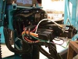
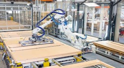
The vertical stabilizers for the tail of the F-22 are assembled at Lockheed Martin’s production facility. Final assembly includes drilling 3459 holes, each of which must be countersunk to a specific depth within a few thousandths of an inch. A custom-made gantry drilling robot designed and built by Applied International Motion (AIM) drills these holes (see Fig. 1). Delta Sigma developed the database that registers the vertical stabilizer to the robot and calculates the correct tool position and tool paths for each of the robot’s six axes.
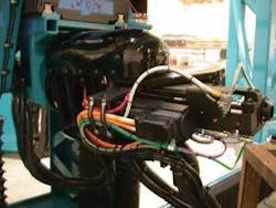
The drilling gantry has an x-y travel of 12 × 12 ft, with 4 ft of z-axis travel. At the end of that positioner there is a drill head that has two rotary axes, plus quill and spindle axes capable of putting a 5/8-in.-diameter hole through titanium. Surrounding the drill bit is a spring-loaded probe, called a pressure foot, which includes a high-resolution encoder (see Fig. 2).
“The most challenging part of this project was getting the countersink depth. Once the vertical stabilizer coordinate system is determined, getting on point and vector is relatively easy. Unfortunately, the surface of the skin is somewhat ambiguous to this coordinate system. The skin surface tolerance is ±0.030 in., but we need to countersink the hole to an accuracy about 20 times better than that. Our depth precision is measured from where the surface actually is, not where it should have been,” says Dan DalColletto, vice president of engineering at AIM.
That spring-loaded probe-the pressure foot-is used to overcome this challenge. The pressure foot measures the location of the skin surface just before the drill bit makes contact with the skin. These data are used to calibrate the drilling robot a few milliseconds before impact. The system works as long as the relative position between the skin and the probe, and the probe and the drill bit, are known.
Precision Measurement
Recently, Lockheed Martin contracted Delta Sigma to assist with a way to use machine vision to verify the relative geometry of the drill head. Delta Sigma designed and built a test system in the lab that duplicates all the critical features. The vision system is incorporated into this test setup.
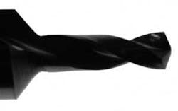
“The key to a successful test is that all of the pertinent questions are answered and that the test environment adequately represents the real world,” notes Brett Haisty, vice president of engineering at Delta Sigma. “Our tests show that the vision system can easily achieve sub-mil (less than one-thousandth of an inch) accuracy on these large cutting tools. We are using a telecentric lens from Edmund Optics, which gives us about a square inch of image area, and a high-resolution camera from Cognex. The drill bits have the countersink about 0.9 in. up the shank, so we can drill and countersink in one motion. The most critical dimension is the pressure-foot face to the countersink. This has always been measured indirectly. Now we can measure it directly.”
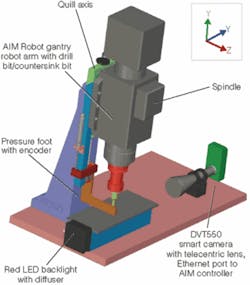
The Cognex DVT550 camera is stationary, located on one side of the drill jig. Haisty says that the vision calibration process causes the robot to move to the camera position and push the drill bit between two bars. At one end of the bars is the DVT550 smart camera with a telecentric lens to eliminate optical distortion; at the other end there is a Cognex IDRA, red LED backlight with diffuser to eliminate hot spots and provide an even field of illumination (see Fig. 3).
The bars stop the pressure foot just as it comes into the camera’s view, but the drill bit extends out beyond the pressure foot and covers most of the field of view. The vision tools in the camera along with scripts written by Delta Sigma then execute the calibration routine.
The calibration routine uses edge detection to find the outline of the drill bit and countersink. Lines are drawn along the sides of the countersink to determine the slope of the countersink and length, shape, and width of the drill bit. Based on the slope information from the countersink portion of the bit, the camera calculates the point of intersection based on the countersink slope below the end of the drill bit.
With this angle and depth information, combined with the process-control information from the database, the exact condition of the drill bit/countersink can be determined and the robot plunge depth adjusted to ensure that the tolerance required for the countersink is met. This is not a measurement that could be made any other way because the actual point of intersection does not physically exist but is still critical to creating holes within the specified tolerance.
One of the problems in high-precision countersink measurements is that there is nothing that is easy to measure. Even the transition from the drill shank to the countersink has a small radius, so there is no edge or point to measure. The beauty of the vision system is that it finds the sloping edges of the countersink and extends them down to their virtual intersection to create a point that is repeatable. Although this point is only mathematical and not real, it is exact and very repeatable from drill bit to drill bit.
Production Line
Currently, the drill bit is placed in a tool holder, where the drill tip is an exact distance from a gauge line on the tool holder. Although this position is not extremely critical, the tip-to-countersink distance is a high-tolerance dimension on the drill bit so the countersink-to-gauge line is thus “known” by the fact that is should be 0.900-in. from the tip. There is also a gauge line on the spindle. The pressure foot was installed at a known distance from the gauge line. So, when the tool holder is placed in the spindle, the gauge lines match (assuming there is not a dust particle inside the spindle), thus providing a pressure-foot-to-countersink relativity. Test coupons of graphite are drilled and measured to verify accuracy of the setup. The drill-system software has a place to enter an offset value if the countersink depth is not correct.
It is often not required, although it is typically off by one or two-thousandths an inch. One problem is that the drill tip and countersink do not wear at the same rate. Dust in the spindle is a real threat. Other factors are undoubtedly at work, plus it is a difficult measurement to make. All of these factors mean that the countersink depth must be checked often, and this takes time.
By making direct measurements between the countersink and pressure foot with the vision system, performance and cost can be improved in several ways. The vision system removes the critical nature of the cutter in the tool holder-the gauge line is no longer important. Dust in the spindle is less important. Perhaps reducing the tolerance on the tip-to-countersink specification of the drill bits will reduce their cost. Also, as an added benefit, we determine that the drill diameter is correct (in case the wrong cutter was loaded in the tool holder) and can inspect for damage to the cutter, as well. This can prevent a costly mistake.
Features, advantages, benefits
Mark Bowen, applications staff engineer at Lockheed Martin, who is heading up the research project, says, “This technology looks very promising. We are trying to put the best tools possible into the hands of our technicians to produce a high-quality product at the best cost. The vision drill-depth calibration project was initiated because a manual measure-and-adjust cycle was being repeated hundreds of times per day. It appears that we can take a task that takes one or two minutes each time and reduce it to just a few seconds. If we can do that and improve our accuracy at the same time, this project could be a tremendous benefit to the F-22 program.”
null
