Advancements in image sensors drive the need for automated alignment of consumer camera modules.
By Justin Roe and Mark Kozak
Digital camera modules are becoming ubiquitous across a range of consumer products. The use of cameras within mobile applications such as mobile phones and automobiles is spurring innovations in pixel density, lens quality, and power usage. As the performance of the camera modules improves, the requirements for assembly techniques increase, as well.
While machine vision is a great improvement over passive (blind) alignment, it still comes up short in aligning lenses because machine vision can only align to physical characteristics (fiducials) on the surfaces of the components. Machine vision cannot take into account the optical characteristics of the assembly in operation-that is, the focusing characteristics of the complete lens/sensor assembly. Automation Engineering (AEi) has developed an automation platform for camera-module assembly and test (CMAT) that significantly advances the accuracy of this alignment process of camera modules and results in increased performance and yield.
Traditional Methods
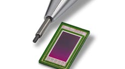
Camera modules consist of two primary components: a CMOS camera sensor on a circuit board and an optically aligned and attached lens barrel assembly. Traditionally, the manufacturing process inserts a threaded lens barrel into the camera housing, with the operator threading the lens barrel into the housing while monitoring the camera image on a video screen to align it. With this type of design, the manufacturer only performs alignment of the lens assembly to the sensor in one dimension-the optical axis. For new generations of camera modules, alignment of the other two linear and two rotational axes becomes critical.
Achieving a sharp image over the full plane of the sensor and throughout the full range of zoom capability requires accurate alignment of the lens to the sensor in not just one but five degrees of freedom. This is becoming more important as camera-module resolutions increase and as consumer expectations of image quality grow. Active alignment of the lens/sensor assembly compensates for variability inherent to upstream manufacturing processes, producing a more consistent product with higher performance and yield (see Fig. 1).

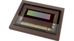
AEi developed the CMAT system specifically to support multiaxis active alignment and assembly requirements for next-generation camera modules. Its main functional blocks are a five-axis alignment stage, camera-interface electronics, optical target and lighting system, epoxy dispenser system, UV cure system, PC-based control system, and control software (see Fig. 2).

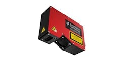
The five-axis alignment stage consists of a three-axis linear stage with a two-axis flexure stage for rotational movement. The stages enable a precision gripper to manipulate the lens. This gripper can pick the lens from a SMEMA conveyor-compatible pallet or from a batch-loaded tray. The interface electronics consist of AEi camera interface electronics along with a National Instruments (NI) 1422 or 1424 PCI high-speed digital image-acquisition card. The camera interface electronics converts the image stream from the camera module into a format compatible with the NI card. It also supports I2C, LIN, and other camera communication bus electrical interfacing and incorporates driver circuitry for voice coil, piezoelectric, liquid lens, and other actuators for optional zoom and focusing mechanisms used in low-power cameras (see Fig. 3).

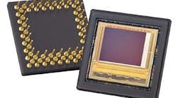
The CMAT system uses optical targets designed to accommodate a variety of lenses and optical tests. The targets incorporate features that provide analyses such as modulation transfer function (MTF), gradient-based focusing, centration, and color analysis over zooms from wide angle to telephoto (see Fig. 4). CMAT applications use LED lighting from Advanced Illumination because of its uniform illumination intensity and color temperature over a long life.

The CMAT station includes an automated epoxy-adhesive dispenser. An EFD liquid-dispenser valve mounted on a three-axis linear stage dispenses the UV-curable adhesive uniformly to a configurable pattern with coordinated motion. Then an EXFO Omnicure UV light source with multiple high-power delivery lightguides ensures uniform and complete cure of the adhesive. The Omnicure system uses a closed-loop feedback system that maintains a consistent power output throughout the life of the UV lamp.
The CMAT FlexAuto software controls the process including image acquisition, optical alignment, and machine control. End users can define multiple recipes to satisfy many product requirements. FlexAuto is an object-oriented, PC-based motion-control and machine-vision application development environment that users can configure to support motion control, machine vision, and human-machine interface (HMI) requirements without training in programming, electronics, motion control, or machine vision. End users can create control and user interface recipes without writing code.
System Operation
The operator begins the camera align and test process by selecting the appropriate recipe through the FlexAuto HMI. The recipe files contain the test and setup parameters for the specific camera and lens combination being built. The camera housing and lens assembly are then loaded into the station using a product-specific pallet.
Once the pallet is loaded, the operator starts the alignment and test process through the HMI display. An SMC guided actuator lifts the pallet upward and accomplishes three important tasks: mechanical registration of the pallet, mechanical registration of the camera module, and electrical connection of the camera circuitry through pogo-style test probes. Then the system applies power to the camera and performs basic electrical functional tests.
The servo-driven three-axis motion stage positions the EFD needle dispenser valve over the camera module and the Galil Motion Control controller is commanded by the FlexAuto software to perform an interpolated move to dispense a continuous bead of UV adhesive along a user-configurable programmed path. The CMAT system uses machine vision to verify the quality of the dispensed bead of adhesive prior to aligning and attaching the lens.

The alignment process begins as the lens is picked from the pallet and placed at a nominal position over the vision sensor. The first step in the process is to center the lens on the sensor below using machine-vision algorithms. The system acquires images of the target and adjusts the lens in thex-y (sensor) plane until the alignment features center on the image (see Fig. 5). It then determines the correct lens height, pitch, and roll required to obtain a uniform focus across the entire image. The system tests the image quality for particle contamination, color fidelity, distortion, MTF, and other characteristics. The final step in the process is to cure the UV adhesive and bond the lens assembly to the camera housing. Cure times vary depending upon the UV adhesive chosen for the process.
JUSTIN ROE is chief operating officer and MARK KOZAK is project engineer at Automation Engineering, Wilmington, MA, USA; www.aeiboston.com.

Features, advantages, benefits
Since early 2006, Automation Engineering has been collaborating with Connaught Electronics Ltd. (CEL), a European manufacturer of high-end electronics systems and subsystems for the automotive market, to deploy modified and enhanced CMAT stations. The stations perform alignment, attachment, and comprehensive functional testing for multiple camera module programs for CEL customers. CEL has been supplying these to automotive customers in Europe and around the world for more than 20 years.
Fergus Moyles, director and general manager at CEL in Ireland, notes, “The CMAT station has proven to be a versatile tool that has been very helpful in meeting challenging customer needs and expectations for more sophisticated and capable vehicle camera systems. Our customers expect and require this high degree of quality and performance from CEL in our driver assistance camera platform for single and multicamera automotive vision systems.”