High-speed cameras speed aircraft design analysis
Andrew Wilson, Editor
Despite the advances in computer-aided design (CAD) and numerical analysis and simulation software, aircraft designers still need to test their designs before they are deemed airworthy. To do so, scale models of aircraft must be built from these CAD models and subjected to high-performance testing in wind-tunnels. By doing so, developers can, under controlled conditions, study the effects how different aircraft designs will perform at various wind speeds.
According to Reinert Müller, President of The FIBUS Research Institute (Hamburg, Germany; www.fibus.org), numerical calculations of lift, drag, acoustics and pressure distribution have never been sufficient to gain a proper understanding of aircraft dynamics. "Rather," he says, "wind tunnel simulations that can capture wind turbulence and vortex flows created by such models can provide a more exact representation of aircraft behavior.
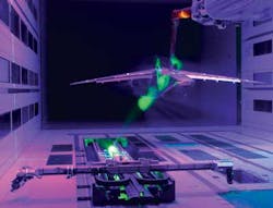
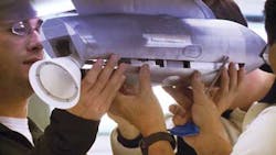
To analyze this behavior high-speed, DNW, the German-Dutch Wind Tunnels (Noordoostpolder, The Netherlands; www.dnw.aero) enlisted The FIBUS Research Institute to develop a system that could capture the motion of aircraft structures (Figure 1). Simultaneously, DNW is equipped with a system that is capable of dynamically monitoring turbulence and vortex effects using an optical flow measurement technique known as particle image velocimetry (PIV). A video of the system in operation can be found at: http://bit.ly/XwfBXL.
Aircraft motion
"To capture the motion of aircraft structure," says Müller, "any deformation in three-dimensional (3D) space must be captured at high-speed." Such performance analysis was required for the development of the Embraer KC-390, a medium-size, twin-engine jet aircraft. As a military transport aircraft, the KC-390 is designed to transport cargo and troops while capable of aerial refueling.
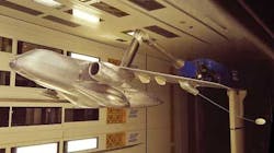
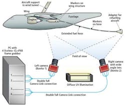
To perform this refueling, the aircraft is fitted with an extensible fuel hose system that extends from the aircraft during flight (Figure 2). "As well as studying the performance of the aircraft itself," says Müller, "it was also necessary to determine any effects the deployment of the fuel hose system would have during flight. Any aircraft trying to get re-fueled can do a successful docking only if the fuel hose is not moving too rapidly."
To accomplish this, markers are first placed on the wing structure of the aircraft and the fuel hose. So as not to influence the airflow across the aircraft, these markers must be less than 10 microns in thickness. In the past, such markers were placed on the aircraft using artwork from Letraset (Ashford, Kent, England; www.letraset.com).
"Now," says Müller, "these markers are applied using yellow signal color ink. Then, by illuminating the aircraft with UV light and using yellow filters on the camera lenses, only the markers will be visible. This makes the task of capturing and processing images much easier."
3D data capture
To capture three-dimensional (3D) positional data from these markers, FIBUS employed a dual-camera stereo system (Figure 3) using two Bonito 4M pixel Camera Link cameras from Allied Vision Technologies (AVT; Stadtroda, Germany; www.alliedvisiontec.com). With a dual-10-Tap Camera Link Deca interface with four connectors, each of these cameras is capable of transferring images at up 400 fps to the host computer. To do so, each camera requires two Xcelera-CL+ PX8 PCI Express frame grabbers from Teledyne Dalsa (Waterloo, Ontario, Canada; www.teledynedalsa.com).
"For real-time tracking applications," says Müller, "it is necessary to transfer images from the cameras to the host PC's image buffer at high-speed with little or no CPU-overhead. Because the Bonito camera employs the AM41, 4/3in 2336 x 1728 CMOS imager from Alexima (Pasadena, CA; www.alexima.com), the camera can be configured to simultaneously transfer two 1120 x 1728 images to each of the two frame grabbers. Using the frame grabbers in a special ‘child buffer' mode, both these images are then DMA'ed into the memory buffer of the host computer resulting in a single image and no processing overhead.
DNW developed a 2kW high-power LED UV illumination source capable of illuminating approximately a 10 x 10m area of the aircraft under test. With such an illumination source and a camera exposure time of 2.5ms, however, markers could not be properly distinguished. To overcome this, a 5ms exposure time was used resulting in image capture speeds of 200fps.
Computing positions
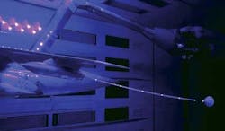
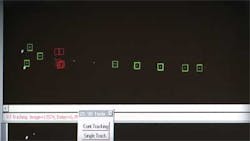
After the stereo camera system is calibrated, captured images are transferred to the host PC for processing. Rather than performing feature analysis of each complete image, known regions of interest (ROIs) within each image were first set on the wing and on the fuel hose extension structure (Figure 4). While the fuel hose was extending during the test, additional ROIs would be positioned automatically on the markers on the fuel hose as soon as they became visible. These ROIs are flexible and can move or even grow from image to image. Images of the markers within each ROI were then thresholded and a calculation performed to find the center of gravity (COG) of each. Two-dimensional COG data was then used to reconstruct 3D data of the fuel hose motion.
Of course, should the fuel hose move to rapidly, the ROIs cannot follow the markers anymore and some of the markers may move outside the ROIs. Should this happen, the COG of the markers cannot be determined (this is shown in red in Figure 4). "To ensure this does not occur," says Müller, "it is important to make the ROIs small enough so that the COG of the markers can be computed rapidly, while at the same time large enough so that the markers will not move outside the ROIs within the short 5ms from one image to the next.
To expedite this processing, FIBUS used a Quad-core Intel-based CPU to partition the tasks of determining the COG, perform 3D reconstruction of the co-ordinates from both camera systems and generate a graphical overlay of these positions. Software to perform this processing was developed in C. In this way, any movement of the fuel hose can be captured in real time while it is extending to its full length. These measurements were performed under a number of different wind speeds and other boundary conditions.
Since a typical wind-tunnel test run may take several hours, only the computed 3D co-ordinate data is captured by the system. In this way, only a relatively small 1200MByte file is required to store the image data rather than the over 50TBytes that would be needed to capture complete image sequences.
Particle image velocimetry
To understand the complex motion of the fuel hose at different flight speeds of the aircraft, engineers at DNW built a system to measure the airflow behind the wing using PIV.
"By seeding the airflow with minute particles of oil or other special fluids, and capturing their behavior as they move across the aircraft, flow structure and turbulence or vortex effects can be visualized and measured quantitatively," says Müller.
The design of this PIV system follows a similar stereo approach to that to measure the aircraft markers. However, rather than illuminate the aircraft model with UV light, a 2mm laser light sheet set up perpendicularly to the main flow direction was used to highlight the particle flow.
To capture images of the particles, data from two calibrated PCO2000 cameras from PCO (Kelheim, Germany; www.pco.de) was transferred over a 50m fiber-optic interface to a host PC.
"To compute the vector flows of the seeding particles, images needed to be captured at high-speed," says Müller. "To do so, each of the cameras captures double frames at two double-fps from a different view point."
The interframing time of each double frame is set to a very short time value in the range of 15..20us. "This technique has also been used by Numetrix Technologies (Sherbrooke, Quebec, Canada; www.numetrix.ca) in the design of its NX3D series of high-speed image scanners (see "Digitizer captures 3-D images at fast data rates," Vision Systems Design, July 2012, pp.13-16; http://bit.ly/LwRweO).
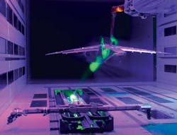
By analyzing these stereo pairs of images, the speed and direction (velocity vectors) of the flow can be calculated in 3D space using software from PivTec (Göttingen, Germany; www.pivtec.de)—see Figure 5. In this figure, the computed vortex is close to the path of the extended fuel hose and its position changes depending on the speed of the aircraft. Therefore, the vortex can have a strong influence on the hose during certain flight conditions.
Acknowledgement
The author would like to thank Dr. Reinert Müller, President of The FIBUS Research Institute and Frenk Wubben, Project Manager of the German-Dutch Wind Tunnels for their help in preparing this article.
Company Info
The FIBUS Research Institute
Hamburg, Germany www.fibus.org
DNW, the German-Dutch Wind Tunnels
Noordoostpolder, The Netherlands www.dnw.aero
Letraset
Ashford, Kent, England www.letraset.com
Allied Vision Technologies
Stadtroda, Germany www.alliedvisiontec.com
Teledyne DALSA
Waterloo, Ontario, Canada www.teledynedalsa.com
Alexima
Pasadena, CA www.alexima.com
PCO
Kelheim, Germany www.pco.de
Numetrix Technologies
Sherbrooke, Quebec, Canada www.numetrix.ca
PivTec
Göttingen, Germany www.pivtec.de
Vision Systems Articles Archives
