Vision system makes predictive maintenance of machine tools a snap

Andrew Wilson, Editor
Today's computer numerical control (CNC) machine tools are essential for machining of the often complex components used in the aircraft, heavy equipment, and automotive industries. To perform specific machining tasks, such systems employ hundreds of tools such as drills, taps and special cutting tools that are automatically selected from tool holders in the machine. Because such systems are fully automated, it is essential that the system must be aware of whether a specific tool is broken or worn before machining operation can take place.
"Today," says Gerald Budd, President of Phoenix Imaging (Livonia, MI; www.phoeniximaging.com), "there are several methods to accomplish this task." For example, while mechanical touch probes or laser detectors can be used to ensure that the tool is present, measuring the torque on the motor can determine – to some extent – the amount of wear on the tool.
"However," says Budd, "in neither of these cases, can the system be used to determine whether a tool may be chipped or damaged. Should chipped, worn or improperly centered tools be employed, this can result in improperly machined parts that may need to be reworked or even worse, scrapped further along the manufacturing process."
More importantly, perhaps, is that mechanical touch probes or current measurement systems cannot be used to perform any predictive maintenance assessment on the tools themselves. This is especially important in the aerospace or automotive industry, where the lifetime of expensive, high-performance tools may need to be assessed.
System design
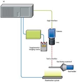
To perform this task, Phoenix Imaging has developed and patented a machine vision system known as the CNC-Tool Status Advisor (a.k.a. CNC-TSA). Several possible implementations of the instrument have been developed that depend on the tool inspection requirements (Figure 1). In the most basic design, a single camera, image processor and illumination system is mounted in a fixed position with respect to the tool being inspected. One or more sensors may be required for the inspection depending on the variation in the length of tools being inspected.
The system consists of a LED backlight positioned on the opposite side of the tool and tool holder and a camera positioned a fixed distance from the centerline of the tool (Figure 2a). Image data from the camera is transferred to Phoenix Imaging's PC-based PVS-80 vision controller. This can be interfaced to one or more cameras and is capable of inspecting multiple features simultaneously, such as multiple views angles of the end-tip and/or the shaft of the tool.
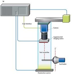
If the tools in the CNC machining center vary greatly in length, it is more economical to use a single sensor and reposition it to examine the tip-end of the tool. This is performed by mounting the sensor on a translation device that moves the sensor and illumination system from a rest point to an inspection point and back again. This movement between points can be very depending on the speed of the tool changer (Figure 2b).
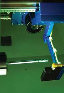
To capture images of the tool, Phoenix Imaging has teamed with Datalogic (Bologna, Italy; www.datalogic.com) to produce a smart sensor rated IP67 to withstand the harsh environment of the CNC machining center. To illuminate the part, the system uses a Phoenix Imaging Model 4500-30/30G, a sealed 30mm × 30mm × 12 mm unit, that produces a uniform green illumination field that is larger than the largest tool diameter to be inspected.
"Depending on the configuration requested by the CNC user," says Budd, "different GigE cameras from Datalogic (Bologna, Italy; www.datalogic.com), Basler (Ahrensburg, Germany; www.baslerweb) and Sensor Technologies America (Carrollton, TX; www.sentechamerica.com) can be used. These cameras are used to capture images of the tool as the translation stage moves along the part and, if required, a second camera and ring light can be added to highlight edge imperfections down the tool axis." The core customer requirements determine the sensor resolution implemented. If the customer only needs to determine that a tool is present and not a catastrophic break then the sensor resolution may be minimal. However, if the customer requires the detection of a worn tool then the sensor resolution must be much higher.
Image analysis
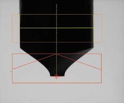
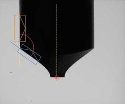
After images of the tool profile are captured, critical tool features are measured. The centerline of the tool is calculated by finding the left and right edges of the tool (Figure 3). This also provides a measurement of the tool diameter (yellow horizontal line). The tool length is shown as a red line at the tip of the tool and its intersection with the tool centerline as the red circle with a cross hair at its center.
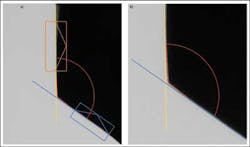
Tool edges are determined in a method similar to that used for finding the tool diameter. Figure 4 shows the location of the left tool edge (yellow line in the orange box) and the leading edge of the left flank (dark blue line in light blue box). The yellow and dark blue lines are extended to intersect and the angle between them is determined (red arc). "The edge measurements of a tool are a better representation of the tool characteristics than a simple comparison of an image before use and image after use," says Budd.
"Should any wear occur," says Budd, "then the angle between these edges will change and the amount of wear can be measured." If this wear is deemed acceptable, then the CNC machining is allowed to proceed. If not, then the operator is alerted that a worn tool may be present.
Figure 5 illustrates how this measurement is performed. A line is fit to a major portion of each edge of the tool and projected until the lines intersect; this is the theoretical intersection point (intersection of yellow and blue lines). A second set of lines is fitted to a shorter portion of the tool edge in the vicinity of the theoretical intersection point referred to as the physical intersection point (Figure 5b). The system determines the minimum distance between the theoretical intersection point and the physical intersection point. If this distance exceeds a customer specified maximum value then the tool is considered to have excessive wear and removed from service.
"At first," says Budd, "it was though that a simple template matching algorithm could be used to perform this task. However, such algorithms were not robust enough to accommodate any apparent changes that may occur in the image of the too tool due to water, dust or the presence of extraneous matter."
As well as predicting tool wear, the system can also be used to determine, for example whether small defects such as chips or breakages may be present. To accomplish this, the system can be programmed to learn the profile of each tool and, by extracting pertinent edge information, build a database of known good parts and their characteristics.
Machine tools can be placed in the tool holders using several methods including inserting the tool into a collet (or chuck) to hold the tool in place. Alternatively, the tool holder can be heated until it expands, the tool inserted and the tool holder left to cool and shrink to hold the tool in place. With either method, the tool is pre-positioned in the tool holder for examination before use. If the tool has an RF tag, the tool properties can be learned in tool set up room and transferred to the machine vision system in the CNC machining center when the tool is inserted.
Commercial implementations
To commercialize this technology, Phoenix Imaging has teamed up with MAG (Sterling Heights, MI, USA; www.mag-ias.com) a supplier of CNC systems. "Instead of waiting for the product inspection area to reject a part due to dull, worn or broken tools, the vision system measures the number of operations performed and wear of the tools. Thus, preventing and or reducing scrap and unnecessary downtime," says Larry Pfeifer, a Product Specialist at MAG.
Phoenix Imaging offers several confi- gurations of the CNC-TSA systems. The configuration selected for a particular project depends on the shape and size of the cutting tools. Sometimes more than one camera is required to view the tool to insure that a flaw is not hidden. For example, a multiple fluted tap may be inspected as acceptable to one sensor, but found as damaged to a sensor mounted in a perpendicular orientation. Large multiple cutting tool heads may require different cameras, illumination and positioning systems.
In its simplest incarnation as a broken tool inspection system, the Tool Status Advisor can be retrofitted to an existing CNC machine at a cost not much more than older mechanical or laser technology if sensor translation is not required. A more sophisticated version of the CNC-TSA system that includes the sensor translation starts around $12,000. Considering the cost of machining multiple high value components only to find damage caused by a defective tool such technology offers rapid payback.
Company Info
Basler
Ahrensburg, Germany
www.baslerweb
Datalogic
Bologna, Italy
www.datalogic.com
MAG
Sterling Heights, MI
www.mag-ias.com
Phoenix Imaging
Livonia, MI
www.phoeniximaging.com
Sensor Technologies America
Carrollton, TX
www.sentechamerica.com
Vision Systems Articles Archives