Augmented vision system aids the sight impaired

Andrew Wilson,Editor
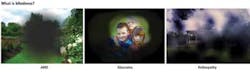
While there is a common misconception that a blind person has no sight whatsoever, a person can be considered blind if they must use alternative methods to engage in any activity that persons with normal vision would perform using their eyes. Indeed, while approximately 30,000 people in the UK have no sight whatsoever, others suffering from such diseases as age related macular degeneration (AMD), glaucoma and retinopathy may also be considered legally blind.
Each of these diseases affects a person's ability to visualize the world around them in different ways. While AMD gradually destroys the macula, the part of the eye that provides sharp, central vision needed for seeing objects clearly, people with glaucoma slowly lose their peripheral vision. Those with damage to the retina of the eye (retinopathy) lose their sight across their field of view (Figure 1).
In the past, people suffering from these conditions relied on guide dogs and white canes to assist them. Today, however, researchers are aiming to develop novel methods such as retinal implants and augmented vision systems to increase the visual acuity of blind people.
Retinal implants
In diseases such as retinitis pigmentosa (RP), a large part of the retina remains functional even after a person loses their sight. Although the rods and cones that convert light into nerve signals are destroyed by this disease, most of the retinal nerve tissue remains intact. Because of this, sub-retinal implants can be used to convert light into electrical signals to stimulate the retinal nerve tissue.
This is the concept behind a number of retinal implants such as the one developed by Retina Implant AG (Reutlingen, Germany; http://retina-implant.de). The company's Alpha IMS is a sub-retinal implant consists of an IC of approximately 3 × 3 mm in size and 70-μm thick and with 1500 individual pixels. Each of these pixels contains a light-sensitive photodiode, a logarithmic differential amplifier, and a 50 × 50-μm iridium electrode into which the electrical stimuli at the retina are guided (Figure 2).
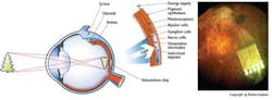
The IC is positioned on a thin, flexible circuit board of polyimide that is connected to a thin, coiled cable that passes through the orbital cavity to the bone of the temple and from there to a point behind the ear, where it is connected to a power supply. Electrical energy is received inductively from the outside through a second coil located on the skin.
Because the electrical excitation invariably involves a number of cells, patients with these implants cannot visualize objects sharply, but are nevertheless able to locate light sources and localize physical objects.
Assisted vision
While such retinal prosthetics somewhat alleviate conditions such as retinitis pigmentosa, Dr. Stephen Hicks at the Nuffield Department of Clinical Neurosciences at University of Oxford (Oxford, England;http://bit.ly/1624Mkc) developed a system to look at ways of improving the image on the low-res implanted devices (http://bit.ly/151VEMv).
The system, known as a Retinal Prosthetic Simulator, first captures an image of a scene and then, by preprocessing the image extracts salient features within it that are then down-sampled and presented visually to the user through a pair of eyeglasses. In the initial prototype, these visual images were acquired using a 752 × 480 pixel Firefly MV FireWire camera from Point Grey (Richmond, BC, Canada;www.ptgrey.com) at a frame rate of 60 fps. Attached to a Z800 3Dvisor head-mounted display from eMagin (Bellevue, WA; www.emagin.com), the camera acquires the scene in front of the subject and these images are transferred to a PC over the FireWire Interface.
At the same time, horizontal and vertical eye positions were acquired at 250 Hz using a JAZZ-novo eye tracker from Ober Consulting (Poznan, Poland;www.ober-consulting.com) worn under the head-mounted display. Data from the eye tracker was then used in conjunction with the visual data to determine the image displayed on the head-mounted display. Before such data could be displayed, however, the captured image was first converted to greyscale and down-sampled to a 30 x 30 image using LabView Vision from National Instruments (Austin, TX, USA; www.ni.com). In this way, features appearing in the image appear sharper and thus more apparent to the user.
Despite this, Dr. Hicks and his colleagues realized that the system was rather cumbersome and difficult to use. Furthermore, the system was incapable of providing any depth perception, making it difficult for the user to judge how far away any specific object or obstacle might be. Because of this, it was decided that a system that provided the ability to locate nearby objects and allow obstacle avoidance at walking speed would be more useful.
Depth perception
To develop this system, an infra-red depth camera from Primesense (Tel Aviv, Israel;www.primesense.com) was mounted on the bridge of a head mounted display and data from the camera transferred over a USB interface to a portable computer. By projecting an array of infrared points onto nearby surfaces and analyzing the returned displacement data, a depth map can then be created that indicates the position of nearby objects.
Using LabView Vision from NI, this depth map was then transformed into a viewable image by converting the distance information into brightness so that closer objects appear brighter. This information was then down sampled and displayed on an RGB LED an array of 24 × 8 color LEDs (Figure 3). To diffuse these individual points of light, a semi-transparent film was inserted in front of the LEDs.
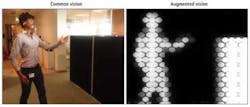
To evaluate the effectiveness of this design, sight impaired individuals were shown to quickly and accurately detect people at a distance of up to 4 m. After a short period of using the system, almost all could recognize nearby objects such as walls, chairs and their own limbs.
Residual information
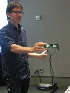
While effective, however, Dr. Hicks and his colleagues recognized that one of the limitations of an opaque display would prevent the wearer from using any of their remaining sight to see the outside world. In age related macular degeneration, for example, a person may still perceive information from their peripheral visual field. Combining this information with stereo depth information would then allow a visually impaired person to more accurately determine information about their surroundings.
Because of this, it was decided to replace the LED display used in the previous design with a transparent organic light emitting display (OLED) from 4D Systems (New South Wales, Australia;www.4dsystems.com.au). Once again, an infra-red depth camera from Primesense was used to capture information and distance information transformed into brightness so that closer objects appear brighter. By displaying the generated image on two transparent 320 x 240 pixel displays mounted in a pair of glasses, however, the user is presented with depth information and a visual image (Figure 4).
Augmenting the capability of the display is just one area where such systems will be improved. Indeed, one of the leading desires of the visually impaired is the wish to read. With this in mind, Dr. Hicks and his colleagues have also demonstrated systems using Point Grey cameras and a text to speech synthesizer software from Ivona Software (Gdynia, Poland;www.ivona.com) that can translate on-line text to speech.
At present such visual aids for the sight impaired are still bulky, requiring host computer processing and 3D camera peripherals. As such systems evolve, however, it may soon be possible to integrate such peripherals into a single pair of glasses that can be produced at low-cost. With such advances, the hundreds of thousands of people that now suffer from such diseases as age related macular degeneration (AMD), glaucoma and retinopathy will be given expanded visual capabilities.
Company Info
4D Systems
New South Wales, Australia www.4dsystems.com.au
eMagin
Bellevue, WA www.emagin.com
Ivona Software
Gdynia, Poland www.ivona.com
National Instruments
Austin, TX www.ni.com
Nuffield Department of Clinical Neurosciences at University of Oxford
Oxford, England http://bit.ly/1624Mkc
Ober Consulting
Poznan, Poland www.ober-consulting.com
Point Grey
Richmond, BC, Canada www.ptgrey.com
Primesense
Tel Aviv, Israel www.primesense.com
Retina Implant AG
Reutlingen, Germany http://retina-implant.de
Vision Systems Articles Archives