Medical wells scrutinized by high-speed automated vision system

James Taylor and Matt Wilton, Industrial Vision Systems Ltd, Oxford, UK
In the past, the process of checking trays of plastic wells used in microwell plates was carried out manually by operators who removed trays from a conveyor belt on a production line to visually inspect them. However, the subjective nature of the operation meant that the process was prone to human error.
So when a UK medical manufacturer decided to automate the inspection of its plastic wells, it turned to engineers at Industrial Vision Systems (IVS, Oxford, UK; www.industrialvision.co.uk) to build an automated special purpose vision machine specifically for the purpose, including full validation to GAMP5 (Good Automated Manufacturing Practice) pharmaceutical regulations.
Microwell plates typically have ninety-six white plastic wells arranged in rows that are used as small test tubes in laboratories to analyze cell cultures. During a multi-stage production process, the wells are coated with active chemical compounds. In use, these compounds bind to specific targets when serum or plasma is deposited in the wells. When they do, they cause color changes that can be detected by medical instruments to test for presence of disease.
Ensuring the consistency of the color of the coated white plastic wells is important to ensure that when they are used, the color change detected by the medical instrumentation provides a reliable indication of the chemical changes taking place in the sample.
The issue is compounded by the fact that chemicals used in the coating process are themselves colored. Although the chemicals should be washed from the wells in the production process, if any remain, when serum or blood is tested for disease, the instrumentation could produce erroneous results. Aside from ensuring the consistency of the color of the wells, detecting any particulate matter that might remain in the well as a result of the production process is also vital to ensure the accuracy of such tests.
Interior and exterior
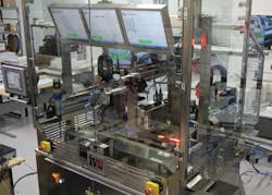
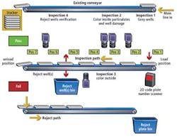
In the design of the IVS system, four vision-based inspection stations check the interior and exterior color of the wells, and ascertain whether any particulates are present. Once any wells that fail to meet the manufacturer's specification are removed from the tray by the system, a final vision check is performed to ensure the reject process was successful (Figure 1).
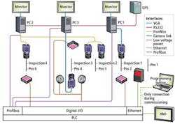
In operation, each individual tray of ninety-six wells is picked off an existing conveyor line by a custom pick and place unit that uses a combination of pneumatics from Festo Pneumatics (Esslingen, Germany; www.festo.com) and an Allen Bradley (Milwaukee, WI, USA); www.rockwellautomation.com) linear axes drive. At a rate of one every three seconds, the unit places them onto a servo-controlled walking beam system that employs multiple grippers which engage the trays from either side and indexes them sequentially through the vision inspection, well removal and tray removal stations (Figure 2).
Prior to the first inspection, an SR651 data matrix scanner from Keyence (Osaka, Japan; www.keyence.co.uk) reads a data matrix code on the outside of the plastic tray containing the wells and transfers the data over an Ethernet interface to an Allen Bradley CompactLogix PLC. In this way, each tray can be tracked through the process, so that if any faulty wells, or faulty trays of wells, are identified by the vision system, they can be removed from the line at a later stage. In addition, all data and results are transferred to the customer's master database.
Gray levels
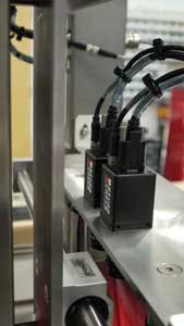
At the first vision inspection station, the coated, plastic wells are inspected to verify that their whiteness falls within a given specification. To do so, the station employs an L103 1k monochrome line scan camera from Basler (Ahrensburg, Germany; www.baslerweb.com) fitted with a Qioptiq Rodogon (Asslar, Germany; www.qioptiq.com) 105mm f/5.6 lens. This camera is mounted inside a stainless steel shroud to shield it from ambient light (Figure 3).

As the shroud containing the camera transverses the top of the tray of wells under servo control, the bottom of the tray is illuminated by a high intensity MBRC red line light from SCHOTT Moritex (Saitama, Japan; www.schott-moritex.com) which moves in synchronization with the camera.
The gray scale check is one of the key functions performed by the vision system. The monochrome line scan camera chosen for the task enables high resolution images to be captured and processed in an acceptable one second time frame, while the single wavelength red line light provides consistent lighting across all of the wells.
An image captured by the line scan camera from above a tray of wells is transferred over a Camera Link interface to one of three Intel i7 industrial PCs in the system where the image is processed using NeuroCheck software from Neurocheck GmbH (Remseck, Germany; www.neurocheck.com).
The NeuroCheck software then consecutively computes the gray scale intensity of the areas in the image bounded by the circular edge of the wells. More specifically, it calculates the maximum and minimum gray scale intensity, the average and the standard deviation from the average.
Having done so, the gray scale intensities are compared to a template of acceptable gray scale values. This template is created during system set up by teaching the system what range of gray scale values are unacceptable by capturing images of failed parts. Should one or more of the wells fail the inspection, the location of the well within the tray is transferred over an Industrial Ethernet/IP network to the PLC which logs the details.
Color check
Having inspected the inside of the wells for gray level intensity, the tray of wells is indexed by the walking beam system to the second inspection station. Here, the wells are checked to determine whether any colored compounds are present and that there is no particulate matter inside them (Figure 4).
To do so, this vision inspection station uses two NeuroCheck NCF120c area-scan cameras fitted with a 25mm f1.4-22 Pentax lenses from Ricoh Imaging (Tokyo, Japan; www.ricoh-imaging.co.jp). Housed in a stainless steel shroud, the cameras each capture an image of one half of the top of the tray of wells through an on-axis flat dome light from IMAC Machine Vision Lighting (Moriyama, Japan; www.kkimac.jp). This light requires only a fraction of the space of traditional dome lights, while providing the desired wide angle of illumination.
Images captured by the two area scan cameras are transferred to a second Intel i7 based PC over a FireWire interface for processing. NeuroCheck software analyzes the same regions of interest in the images that were analyzed during the grey scale analysis process - namely the area within the inside of the wells. At this stage, however, the images are checked for color consistency.
To do so, the system is first calibrated by presenting the system with a number of reject parts. RGB values of those images are then used to create a template of color values. During operation, the software compares the RGB values of the images of the wells with the range of template color values to determine whether a product falls within a given tolerance range.
At this stage, the interior of the wells are also checked to determine if any particulate matter has been left in the well during production. To do so, the NeuroCheck software performs a thresholding operation on the image to separate the image background with regions of the image that correspond to any foreign objects. If a well fails due to its unacceptable color, or because of the presence of particulates, the location of the well in the tray is transferred over the Profibus network to the PLC.
The tray of wells is then indexed to a third vision inspection stage where the colors of the underside of the wells are inspected (Figure 5). To do so, an image of the bottom of the wells is captured with a Basler L304KC color line scan camera fitted with a TC16M080-88.4mm telecentric lens from Opto Engineering (Mantova, Italy; www.opto-engineering.com). As the camera transverses the underside of the tray, it is illuminated by a backlight from above and a fiber-optic light from below which moves in synchronization with the camera.
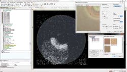
The image of the underside of the wells is transferred to a third Intel i7 industrial PC over a Camera Link interface. Here, the NeuroCheck software identifies the areas in the images that represent the bottom of the wells and compares the color in the images with a second template that represents a range of reference colors in RGB color space. As before, if any well fails the inspection process, the location of the well within the tray is transferred to the PLC.
Rejection and verification
Having verified the color consistency of the wells and inspecting them for contamination, the tray of wells is then indexed to a fourth station where any unacceptable wells are removed (Figure 6).

To do so, the system employs a servo-controlled electromechanical actuator fitted with a custom built pneumatic system with ninety six heads that can each be actuated individually. In operation, the head is moved over the tray of wells, and under control of the PLC, a vacuum is applied to one or more of the heads to remove any defective wells from the tray. Having picked out any faulty parts, the actuator moves the head over a reject bin, the vacuum is removed, and the wells are deposited into it.
The walking beam system then indexes the tray of acceptable parts to a fourth inspection station where the system verifies that the rejected parts have been removed from the tray. To do so, the tray is lit from beneath by an IMAC LED backlight while a NeuroCheck NCF113 area scan camera fitted with a Pentax lens captures an image of the top of the tray.
The image is then transferred over a FireWire interface to the second PC, which, in addition to processing the images from the second vision inspection stage, also performs a gray level analysis on the image. This enables regions in the image that differ in brightness compared to areas surrounding them to be identified, resulting in the identification of the location of any missing rejected wells.
Pass or fail results from the verification stage are transferred over the Profibus network to the PLC. If all the failed wells have been removed from the tray, the PLC instructs a second servo-controlled pick and place machine to place the tray back onto the conveyor from which it was originally removed, after which the trays are stacked and manually packed.
However, if any of the wells have not been removed, the PLC instructs the same pick and place system to remove the tray from the machine, placing it on a conveyor which transports the tray into a reject bin. The rejection mechanism also enables the manufacturer to reject trays of wells should any other non-vision related failures be identified earlier in the production process.
To visualize the operation of the machine, each of the PCs are connected to flat panel displays with an HMI interface designed within the standard NeuroCheck software that highlights the progress of the vision inspection at each of the inspection stages. To do so, the displays provide a visual indication of which of the wells within the tray have passed or failed the inspection stages by highlighting their location on the tray with either a green or red indicator.
Aside from capturing the data from the vision stations for the purpose of identifying bad parts, data from each of the stations is also transferred over an Ethernet network to a PC which maintains a statistical database that highlights the type of rejects that are occurring. This data provides a means to analyze the effectiveness of earlier stages in the production process.
Since it was installed at the medical device manufacturer in 2013, the vision inspection station has proved its worth, inspecting the trays of medical device wells at a rate of 1,920 parts per minute. The speed of the process and the objective nature of the vision inspection process have eliminated the errors incurred in the manual inspection process that was previously employed.
industrial automation
James Taylor and Matt Wilton, Industrial Vision Systems Ltd, Oxford, UK
Company Info
Allen Bradley
Milwaukee, WI, USA
www.rockwellautomation.com
Basler
Ahrensburg, Germany
www.baslerweb.com
Festo
Esslingen, Germany
www.festo.com
IMAC Machine Vision Lighting
Moriyama, Japan
www.kkimac.jp
Industrial Vision Systems Ltd
Oxford, UK
www.industrialvision.co.uk
Keyence
Osaka, Japan
www.keyence.co.uk
SCHOTT Moritex
Saitama, Japan
www.schott-moritex.com
NeuroCheck
Remseck, Germany
www.neurocheck.com
Opto Engineering
Mantova, Italy
www.opto-engineering.com
Qioptic Photonics
Asslar, Germany
www.qioptiq.com
Ricoh Imaging
Tokyo, Japan
www.ricoh-imaging.co.jp
Vision Systems Articles Archives