Vision assists power steering assembly
Winn Hardin, Contributing Editor
Electric power steering systems help drivers control their vehicles by augmenting the torque they apply to the steering wheel of their vehicles, so drivers only need a modest amount of effort to steer. To do so, electronically-controlled power packs are used to add a specific amount of torque to the rack and pinion system.
Producing these power pack assemblies is a multi-stage process that involves fitting a servo motor with several components as it traverses a production line. At each stage of the process, each motor must be tracked by a 2D data matrix code reader and inspected by a vision system to ensure that the components have been have been fitted correctly.
To accomplish this task, one Tier One automotive manufacturer turned to HAHN Automation (Hebron, KY, USA; www.hahnautomation.com) to automate this process. Compounding the manufacturing and inspection task was that the power packs were assembled in several different sizes to accommodate a range of requirements from a number of automotive OEMs.
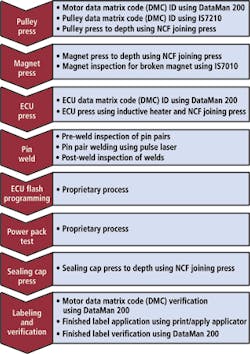
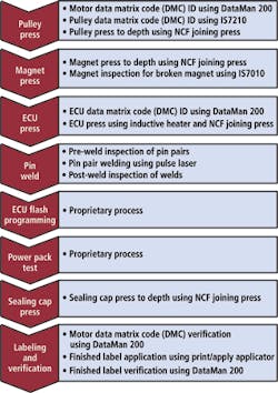
Production of the power pack assemblies involves several key manufacturing stages. First, a pulley is press fit to the shaft of a servo motor to enable the unit to be mechanically connected to the rack and pinion system at a later stage. Secondly, a multi-pole ring magnet is fitted to the shaft, such that the speed and directional information of the shaft can be detected by a sensor and conveyed to an electronic control unit. Lastly, an electronic control unit (ECU) is attached to the motor and the connections between the control unit and the motor spot welded together. After programming and testing, a sealing cap is placed on the motor to protect the unit against the ingress of unwanted material, after which a label is printed and applied to the motor and the data printed on it verified (Figure 1).
Cellular overview
To meet the production line demands of the Tier 1 supplier, HAHN Automation built three MasterCells to produce and inspect the power pack assemblies. In each of the cells, there are two stations that together perform six key tasks. The two stations in the first cell handle the insertion and inspection of the pulleys and the magnets affixed to the drive shaft of the motor. In the second cell, the ECUs are inserted into the motors and the electrical contacts between them are welded together and inspected. At the third cell, sealing caps are inserted onto the motors, after which the motors are printed with a label and the data on the label verified. The programming and testing of the units (which is carried out before the units are sealed) is performed at two proprietary stations developed by the Tier 1 supplier.
The programs that control the operation of the six stations in the master cells in the HAHN systems run on one Siemens (Nuremburg, Germany; www.automation.siemens.com) S7-300 processor. The software dictates the particular recipes-or set of assembly and inspection operations-that are performed on each motor and ECU type according to the type of power pack assembly produced at the stations. This enables the stations in the master cells to be reconfigured to accommodate different models of power pack produced on the production line.
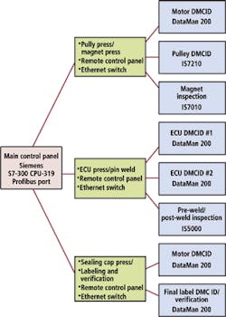
The operations performed at each pair of stations in the three cells are controlled remotely by the main processor. To do so, the processor in the main control unit communicates over a Profibus interface to three Siemens Simatic ET 200S PLC-based I/O systems located at each of the master cells (Figure 2). The I/O modules acquire data from the cameras and 2D data matrix readers at each of the stations through an Ethernet switch, and perform other machine related tasks, such as handling digital I/O. Once the imaging and data matrix code data is acquired from the stations, it is transferred to the main Siemens S7-300 processor for analysis; the CPU then instructs the remote PLC-based I/O units to take the appropriate pass/fail actions at the stations based on the analysis of the data.
On the line
Prior to entering the first of the manufacturing cells, an operator first places an unprocessed motor onto a pallet which is loaded onto a conveyor. A DataMan 200 from Cognex (Natick, MA, USA; www.cognex.com) then reads a 2D data matrix code from a label on the motor so that it can be tracked through each of the production stages. The same code is also affixed to an RFID tag on the pallet to ensure that both the motor and pallet can be identified should they inadvertently become separated during the manufacturing process.
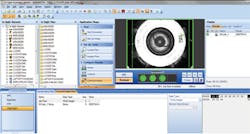
The loaded pallet travels down the conveyor to the first of the MasterCells where an operator loads a pulley to be fitted to the motor onto tooling at a pulley press station. Before the pulley is press fit onto the motor, however, a Cognex IS7000 series camera reads the 2D data matrix code etched into the top surface of the pulley to ensure that the pulley matches the motor type (Figure 3). If it is, the pulley is pressed onto the shaft of the motor using an NC joining press.
Since three different types of pulleys with varying heights are currently included in the various types of power packs that are manufactured at the Tier 1 supplier, the focal distance from the lens of the camera to a pulley's top surface can vary by as much as 4mm. To complicate matters, the camera must be directly over the pulley to read the data matrix code and retract before the press is lowered to press the motor shaft into the pulley.
The changes in focal distance combined with the relatively large field of view, compact space requirements, and lack of available setup time between part types, made the application a suitable fit for the Cognex IS7210 auto focus camera. This was programmed to read the 2D data matrix code using Cognex's Easy Builder software. To allow the camera to retract, the IS7210 was mounted onto a small pneumatic cylinder. After a pulley is placed in the tooling fixture, the cylinder strokes forward and the IS7210 acquires the image which is then analyzed. The cylinder then retracts and the press operation is completed.
Once the pulley has been joined to the shaft of the motor, the conveyor carries the pallet containing the motor into a magnet press station which is also located in the first master cell. Here, an operator places a circular magnet into the tooling which is then press fit into the top of the shaft of the servo motor. In the pressing process, however, magnets can occasionally break, or chip on a spot around their circumference. Hence, a fixed mounted camera was required to acquire images of the magnets to determine their condition after they have been press fit onto the motor.
Since motor heights vary by as much as 56mm across all of the model types, it was necessary to integrate an auto focus IS7010 camera to capture crisp images of the magnets pressed into all of the servo motor types, from the shortest to the tallest. The auto focus feature eliminated any need to refocus or reposition the camera during model type changeovers.
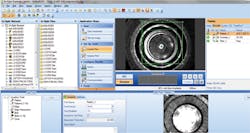
The magnet inspection camera was also programmed using Cognex's Easy Builder software. A pattern match tool was used to find the top of the shiny, center pin of the magnet which enables it to be attached to the shaft of the motor. The acquired image is then filtered to remove any bright or hot spots on the surface of the magnet. This image is then analyzed to detect magnets that are damaged or chipped along the circumference (Figure 4).
If the motor passes the magnet inspection stage, it is conveyed to a second master cell where an ECU is press fit onto it. Prior to fitting the ECU to the motor, however, a DataMan 200 data matrix code reader reads and records the serial number and type number of the ECU that has been loaded into the press. This is then matched to the data matrix code of the motor to ensure that the ECU is of the correct type to be fitted to the motor.
To guarantee that the ECU is tightly fitted to the motor, the motor is first inductively heated by a conductive ring which is placed around its outside diameter. The ring then retracts and the ECU is then pressed into the motor. As the motor then cools, it forms a tight fit between the motor and the ECU.
With the ECU affixed to the motor, the electrical pins that connect the ECU to the motor must be spot welded together through an aperture in the side of the motor. To do so, the motor is carried into the welding station, where it is presented to a laser welder which spot welds pairs of pins on the motor to those on the ECU.
Prior to welding, a Cognex IS5000 series- based custom vision system acquires an image of each of the pairs of pins to ensure that the gap between them is within a nominal range. If that range is adequate, a laser from Trumpf (Farmington, CT, USA; www.us.trumpf.com) then welds the pin pairs together. Once completed, the camera then captures a second set of images of the pairs of pins to ensure that the spot welds are present and are within a given set of tolerances.
Having completed the inspection of the pin welds, the motor and its ECU are transferred along the conveyor to a station where the appropriate control algorithm is programmed into the ECU according to its type. The programmed unit is then moved into a test station where the unit is exercised through an umbilical connection to ensure that the unit will deliver the desired torque speed and response when installed in a vehicle.
Once testing is complete, the unit moves into the third of the HAHN MasterCells where a sealing cap is pressed into the aperture of the motor through which the pins were welded earlier in the production process. At this cell, the data from the label applied at the start of the production process is read once again using a DataMan 200 unit and matched with the data on the RFID tag on the pallet to ensure that the motor has not been inadvertently placed on a different pallet during the production process. Having verified that the two sets of data match, a label is then printed that contains the serial number, the type and electrical characteristics of the motor. The label is then applied to a metal plate over the metal cap on the motor using a tamp applicator and scanned with another DataMan 200 reader to verify that the label has been printed correctly. Once the power pack assembly is finished and testing is complete, it is then ready to be married to a rack and pinion assembly before being tested once more prior to shipment.
Companies mentioned
Cognex
Natick, MA, USA
www.cognex.com
HAHN Automation
Hebron, KY, USA
www.HAHNautomation.com
Siemens
Nuremburg, Germany
www.automation.siemens.com
Trumpf
Farmington, CT, USA
www.us.trumpf.com
Vision Systems Articles Archives
