Vision-guided robot speeds optical filter analysis
Andrew Wilson, Editor
Founded in 1991, Chroma Technology (Bellows Falls, VT, USA; www.chroma.com) is one of the United States' largest manufacturers of precision optical filters. Within the company's 28,000 square foot facility, the company designs, manufactures, tests and sells optical filters for specialized imaging markets that include fluorescence microscopy and analysis, spectroscopy, astronomy and machine vision.
"While low-cost colored glass filters can improve contrast in some applications, they are less precise than interference filters that offer nanometer control over which wavelengths are transmitted. For this reason, Chroma Technology has focused its efforts on the design and manufacture of these higher performance filters," says Paul Millman, President of Chroma Technology.
"Chroma started making filters the way all companies made filters in the late 90's," says Millman, "as soft coated laminated assemblies with absorption glass. As our bio tech customers demanded higher throughput and more durable filters, and OEM customers wanted to move away from absorption (colored) glass for RoHS compliance, Chroma adapted and now primarily offers sputtered surface coatings free from absorption glass and epoxy. While some applications and customers still require the use of absorption glass, the percentage is lower each year as we can now fabricate coatings with some of the same benefits absorption glass offers, all within the structure of the thin film."
Today, Chroma Technology uses numerous sputtering machines to produce a range of long pass, short pass, band pass, and multi-band filters. To produce these filters, round or rectangular glass substrates are first placed in a jig and placed in a sputtering machine. Under computer control, a number of inorganic compounds are then sputtered onto the glass in precisely engineered layers.
Characterizing filters
After this process is complete, each of the filters must be characterized before it is shipped to the customer. To measure the light intensity as a function of the light source wavelength requires the use of a spectrophotometer. At Chroma Technology, a number of Cary 6000i spectrophotometers from Agilent Technologies (Santa Clara, CA, USA; www.agilent.com) are used to perform this task. By incorporating a number of different light sources and photo detectors, the instrument is capable of accurately characterizing optical materials across the 190-1800nm spectrum.
Depending on the wavelength range selected and the accuracy required of the spectral trace, this characterization process can take several minutes, requiring an operator to manually load each individual filter into the spectrophotometer, running the diagnostic test, formulating the results and then repeating this procedure for each filter.
Since Chroma Technology manufactures thousands of filters every year, the company recognized that by automating this procedure such repetitive manual labor could be eliminated. Furthermore, this allows batches of filters to be inspected with no operator present, allowing testing to occur overnight.
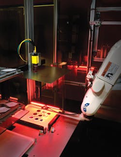
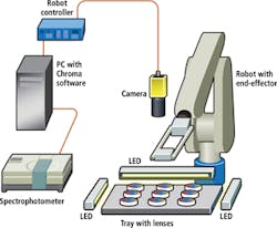
This required a system capable of recognizing a number of different filter types, picking them from a tray, automatically loading them into the Cary 6000i spectrophotometer, characterizing the filter, picking them from the spectrophotometer and sorting them depending on the photometric results. To accomplish this task, Nicholas Day, Systems Engineer at Chroma Technology developed a system that couples a smart camera, off-the-shelf LED lighting, robot and robot controller with the Cary 6000i spectrophotometer (Figure 1).
"As filter batches are produced," says Day, "they are placed on a tray which is then mounted into the inspection system. As each batch of filters may vary in thickness, the operator first manually enters the type of filter, its size and type to be tested into the system's host PC. This ensures that once the picking process begins, the end-effector of the robot will pick the part at the correct height from the tray."
Imaging and robots
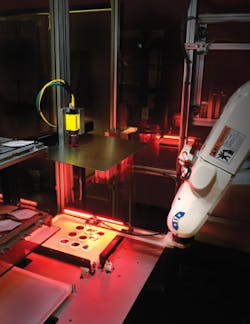
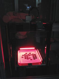
Since the filters are highly reflective, it was necessary to use off-axis to illuminate the parts before they can be imaged. To accomplish this, three red LED bar lights from CCS America (Burlington, MA, USA; www.ccsamerica.com) were placed at the rear and two sides of the tray holder (Figure 2). Since it was necessary to locate the position of the part in the tray for accurate picking by the robot, an In-Sight Smart camera from Cognex (Natick, MA, USA; www.cognex.com) was mounted approximately 18in above the tray.
Using Cognex's In-Sight Vision tools, an image of the tray containing the filters was then captured, thresholded and blob analysis used to determine the centroid of each part. Once each filter's centroid is located, its pixel co-ordinates are translated into x-y space and transferred to a robotic controller that in turn interfaces with a six-axis robot from Denso Robotics (Maryville, TN, USA; http://densorobotics.com).
To pick the filters from the tray, the robot is equipped with a vacuum cup that attaches to filters to be picked using a Venturi transducer. Since each filter must be picked without affecting the surface of the filter in any way, the end effector must be as clean as possible every time a filter is picked. To automatically clean the vacuum cup, a set of clean wipes are placed on a separate tray in the system. Before each wafer is picked, the vacuum cup picks the wipe from the tray and, thus cleans the end-effector. These wipes are then deposited into a chute for manual disposal.
After this process is complete, the first part is picked by this vacuum cup and transferred to the Cary 6000i spectrophotometer for analysis. Before doing so, however, the door of the spectrophotometer must be automatically opened. This is accomplished using a second end-effector attached to the robot. Once the door of the spectrophotometer is opened, the filter is placed within a "V" block located inside the unit. The door of the spectrophotometer is then closed and, once closed, proprietary software is used to perform data collection, analysis, storage, and display of each filter's spectral trace.
Quality Control
Once this testing is complete, the results are analyzed to determine whether each part has passed or failed based on pre-determined criteria. Once complete, the software instructs the robot controller to open the door of the spectrometer and withdraw the part. Both good and bad parts are then separated onto a second tray for further processing. This tray, located close to the tray containing filters to be processed, reduces the cycle time of the system.
Once separated, the filters are then removed from the system. Each good part, along with a chart of each filter's performance characteristics can then be shipped to the final customer. "While the cycle time of the pick and place process is approximately 60s," says Day, "to analyze each individual part can take several minutes." Thus, several hours could be required to test a typical batch of approximately 20 filters.
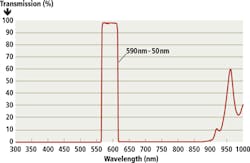
Figure 3 shows a typical output from a band pass filter designed and developed by Chroma Technology that was tested using the automated system. As can be seen, the filter has a bandwidth of between approximately 560-625nm and exhibits sharp roll-off at these wavelengths as well as a high (nearly 100%) transmission ratio between these frequencies.
In the future, Chroma Technology plans to further automate the testing of its filters by adding a bar-code date to each tray. "This," says Day "would eliminate the need for the operator to manually enter data regarding a specific batch of filters and further speed the inspection process."
Companies mentioned
Agilent Technologies
Santa Clara, CA, USA
www.agilent.com
CCS America
Burlington, MA, USA
www.ccsamerica.com
Chroma Technology
Bellows Falls, VT, USA
www.chroma.com
Cognex
Natick, MA, USA
www.cognex.com
Denso Robotics
Maryville, TN, USA
http://densorobotics.com
Vision Systems Articles Archives
