Lucas Willis
One of the most common industrial machine vision applications is gauging - using a calibrated vision system to measure parts for quality inspection. Vision system-based metrology is capable of high precision, non-contact measurements, but even carefully calibrated systems may not always produce the correct measurement values. Measurement errors stem from many sources, such as the change in magnification with working distance that occurs when traditional non-telecentric objective lenses are used. Perhaps the most commonly overlooked cause of measurement inaccuracies, however, is improper illumination.
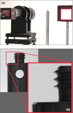
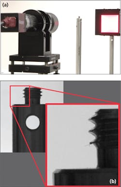
Proper illumination techniques are important in every vision application, but are critical when precision measurements need to be made. Often, a backlight is used to produce a silhouetted image of the object to be measured with the object placed between the light source and the lens (Figure 1). In such configurations, the background is bright and the object is dark when imaged.
There are several possible variations of this configuration since the imaging lens may be fixed focal length, single-telecentric or double telecentric and the backlight may be diffuse or collimated. All of these configurations produce a dark silhouette of the object. However, even when the object imaged is not being measured, but simply identified or checked for defects, there are many cases in which a simple backlight will not suffice.
Depending upon the geometry and surface properties (e.g. reflectivity) of the object, the true form of the object may differ from the theoretical projected silhouette. Diffuse light may scatter from the front of the object, making it appear smaller than it is. This is particularly important to note when measuring the absolute dimensions of an object with curved sides.
Seemingly innocuous bevels on the face of a part may also have the same effect when they present a reflective path from which diffuse light may scatter into the lens. In some cases this can be mitigated by using a properly-sized backlight with an appropriate diffusing angle, but in many cases the only solution is to use a telecentric backlight in place of a traditional backlight.
Backlights and angular diffusion
Simple backlights consist of a light source placed behind an object (e.g. a single light bulb or LED that acts as a diverging point source). This method of illumination is rather impractical in most applications as the resulting intensity profile of the object can vary greatly from the center to the edges of the field of view. In such cases, uniformity of the light will be poor. Such point sources are also highly directional and will cast shadows on the edges of any object, potentially making the observed dimensions of the part larger than they are.
However, in machine vision illumination, a backlight is generally a sheet of a translucent diffusing material which is illuminated from behind. The diffuse transmission properties of the translucent sheet are very important since different materials have different scattering properties. An ideal diffuser takes directional light and scatters it equally in all directions.
The maximum angle of this scattering is referred to as the diffusing angle, and it is not the same with all backlights. A perfect 180o diffusing light will eliminate all side-shadowing effects and illuminate evenly, but will affect the gauging of parts that are not perfectly flat and thin. This is particularly true for drafted/angled parts where an angled side will provide a direct path for light coming obliquely from the backlight to be imaged. Thus, a narrower diffusing angle with better collimation will reduce the amount of light scattering from the sides of the object. Typical diffusing angles are in the range of 20-90o for practical reasons and smaller diffusing angles are generally preferable for backlighting opaque materials.
At present, the illumination source of a machine vision backlight is almost always an array of LEDs due to their inherent advantages over fluorescent bulbs that flicker at a high frequency and must be filtered if the light is to be narrow-band or monochromatic. Unlike point source backlights that exhibit non-uniformity in the form of roll-off from center to corner, low-density LED arrays will exhibit non-uniformity in the form of a ripple in intensity across the area being illuminated. Thus, a high-density array of LEDs is important for good light uniformity.
Theoretically, a collimated light source eliminates the issues which occur when using a diffuse backlight for gauging. A collimated light source with zero divergence emits a beam of light where all rays are parallel, as is typically the case with a laser. However, the same techniques used for collimating laser beams fail to work in illumination due to the size, shape and angular emission characteristics of non-coherent sources. For instance, a simple lens placed with its focal length away from a light bulb will not produce a collimated beam of light, whereas the same technique works fairly well when working with a diverging laser source.
Telecentricity and collimated illumination
In imaging optics, telecentricity refers to a lens design in which the lens has parallel chief rays across the field of view. This is achieved by a particular placement of the aperture stop within the lens assembly such that all off-axis light is blocked, leaving only the light parallel to the imaging axis. When this principle is applied to illumination, the result is a collimated beam of light with very good uniformity and low divergence, and the device is called a telecentric backlight illuminator.
It is important to note that a telecentric backlight illuminator differs from a simple collimator in its optical design. A collimator is generally a single lens placed in front of a pseudo point source, and it projects a non-uniform intensity profile determined by the angular emission of the original source. In contrast, a telecentric illuminator projects the intensity distribution from a small, uniformly illuminated aperture thereby making the intensity profile more uniform and more like that of an ideal, far-away collimated point source. The tradeoff is that a telecentric illuminator is therefore less efficient than a simple collimator, as the aperture eliminates much of the light from the illumination source.
Fortunately, when a telecentric illuminator is used with a telecentric lens, the overall light throughput is extremely high, as light projected from the telecentric illuminator is collected with great efficiency by the telecentric lens. This characteristic allows for the near-ideal, high-contrast silhouetting of an object placed between the light and the lens.
Telecentric illumination in practice
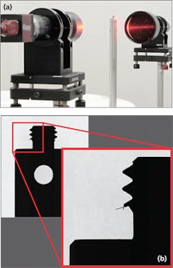
The combination of a telecentric backlight illuminator and a double telecentric lens will produce the best possible image for use with a measurement algorithm (Figure 2). Because the light is well collimated, there will be minimal reflections or scatter from the front of the part and an ideal silhouette will be produced. In this case, parts of dissimilar forms (cylinders and prismoidal objects, for instance) can be measured with the same setup without having to re-calibrate the vision system. This is useful if disparate parts on the same production line need to be measured.
Instead of scatter being the limiting factor, the limitations become diffraction (which can be reduced with shorter wavelength illumination), pixel noise and part presentation, the latter due to projection errors for parts that are not presented perpendicular to the vision system.
Often, vision systems are used to inspect for errors in molded or machined parts rather than make accurate part measurements. In the case of molded parts, the system might need to detect flash left over from the molding process. In the case of machined parts, vision systems may need to check for burrs on parts leftover from machine tooling. Such small features are often invisible when a diffuse light is used, as the illumination causes the small feature to blend into the background. In such cases, a telecentric illuminator and lens combination can be used to highlight such small features.
However, such configurations can be detrimental if the system is used in a dusty environment. Care must be taken to ensure that no dust collects on the illuminator or lens and horizontal mounting or air knives should be used if the environment is excessively dusty. Highly-collimated illumination reveals dust and other particles that are typically hidden by the diffuse light from normal backlight illumination.
Unlike standard backlights which rely on diffusers and multiple sources to manipulate light, telecentric illuminators must generally be large to obtain high uniformity. However, since neither the angular field of view nor the illumination is diverging, fold mirrors can make such telecentric configurations compact. Also, since the light collection in a telecentric illuminator/lens combination is highly efficient, effects dues to ambient lighting are reduced. However, when multiple illuminators are used on the same part for multiple views, it is important to use different wavelengths and use optical filters to reduce crosstalk, or strobe/gate the lights in sequence. Otherwise the quality of the part's silhouette will be compromised.
Lucas Willis, Machine Vision Solutions Engineer, Edmund Optics, Barrington, NJ, USA (www.edmundoptics.com)
