Fritz Bodenand Boleslaw Stasicki
View Image Gallery>>
The efficiency of aircraft propellers is directly affected by the degree to which their shape and local area of attack are deformed during flight. Consequently, the measurement of these parameters can provide valuable information to manufacturers who can then determine how the effectiveness and service life of the propellers can be improved.

Until now, it was only possible to take such measurements by installing strain gauges or accelerometers on the surface of the propeller blade. However, the cabling of these sensors limits the number of possible measurement points and thus prevents true area measurements.
To overcome this, researchers at the DLR Institute of Aerodynamics and Flow Technology (Göttingen, Germany; www.dlr.de) have developed a non-intrusive deformation measurement technique based on the use of vision hardware and associated software that can visualize propeller deformations during flight (Figure 1).

Because the novel vision system is fixed to the propeller hub, it rotates together with the propeller. Hence, the system can measure the deformation of propeller blades as they rotate through 360°.
View Image Gallery>>
Image pattern correlation
The system is based on an Image Pattern Correlation Technique (IPCT) in which images of a propeller captured by two CMOS cameras in a stereoscopic arrangement are processed to obtain the 3D shape of its surface. Since the IPCT is based on the correlation of the two digital images from the cameras, a random dot pattern must first be applied to the surface of the propeller to enable the image processing system to measure propeller deformations.
In addition to the dot pattern, checker board markers are also applied to the surface. These markers provide the system with data about the location of key points on the propeller in relation to the cameras and for the recalibration of the cameras in case of any misalignment issues due to vibrations or deformations of the camera support.
In practice, images of the propeller are captured by the pair of cameras looking at the same field of view but under different viewing angles while the propeller is performing maneuvers in flight. The in-flight images from the cameras are then de-warped and cross correlated by the image pattern correlation software. Because intrinsic parameters such as the focal length of the cameras and extrinsic parameters such as the position and orientation of the cameras are known, the 3D coordinates of the areas with the same dot pattern can then be determined through a process of triangulation (Figure 2).

To accurately process the images, the locations and the optical properties of the cameras must first be determined. This is achieved by calibrating the cameras using a checker board plate of known size placed in the cameras' field of view and recording it in different orientations.
By comparing the measured 3D surface of the propeller under load conditions and under an unstressed reference state while the propeller is at a standstill, the displacement vectors and thus deformations can then be deduced with a high accuracy. If the material characteristics of the observed object are known, the local stress can also be calculated.
View Image Gallery>>
Rotating hardware
To enable the system to capture images of the surface of a propeller, the imaging system was developed so that it could be mounted on a propeller hub that rotates with the propeller in flight.
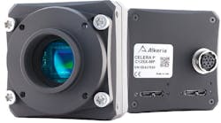
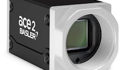
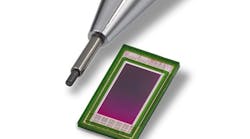
The system hardware consists of a pair of custom built cameras based on 1.3 Megapixel VITA1300 CMOS image sensors from ON Semiconductor (Phoenix, AZ , USA; www.onsemi.com), a retro-reflective photoelectric sensor, a digital phase shifter, an image acquisition system and an embedded computer system with WLAN and GPS capabilities (Figure 3). The system is powered by four rechargeable LiFePO batteries custom designed and manufactured by LRP (Schorndorf, Germany; www.lrp.cc). They can provide 80 minutes of continuous image recording with a maximum speed of 45 image pairs per second.
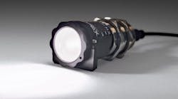
The FR 10-RL retro-reflective photoelectric sensor from Sensopart (Gottenheim, Germany; www.sensopart.com) is mounted on the hub of the rotor and aimed at a reflector on the cowling. As the hub rotates, one trigger pulse is created for each revolution of the propeller. Depending on the setting of the phase shifter, a stereoscopic image pair is recorded directly at the same instant of time as the trigger pulse, or with a specific delay.
The images captured by the two CMOS cameras are transmitted to an embedded Intel Core i7 processor-based PCIe/104 single board computer built by ADL Embedded Solutions (San Diego, CA, USA; www.adl-usa.com) via two GigE interfaces and stored on an integrated 1.8in solid state disk (SSD). In addition, data from an integrated commercial GPS receiver simultaneously logs the position of the aircraft and the time at which the image was taken.
The cameras, the frequency independent digital phase shifter and the system control software were designed and manufactured in cooperation with HARDsoft (Krakow, Poland; www.hardsoft.pl).
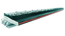
To resist the extreme centrifugal and vibrational forces present during the rotation of the hub of the aircraft, all the electronics for the system were fixed in rigid metal enclosures to prevent damage. The metal enclosures were then stacked and linked by rods to form the complete system (Figure 4).
The system allows researchers on board the aircraft to start and stop the imaging from the cabin via the WLAN network, review the images and examine them directly in the cabin of the aircraft during the flight test. If necessary, they can also remotely modify the image acquisition parameters of the system.
The phase shift, for example, can be set to a constant value, enabling the system to record the propeller at the same position for each revolution independent of the propeller speed. The programmable phase shifter also enables the system to work in a stroboscopic mode which can be used to investigate repeatable events. If the phase shift is changed slowly, the periodic events can be stored in real time on the SSD as sequences of images and displayed on the screen in slow motion.
After a flight, the batteries and the SSD with the acquired images can be replaced and the next flight test can be started. The data stored on the SSD can then be post-processed with the IPCT software on a separate computer.
View Image Gallery>>
Flight testing
Once the development of the rotating camera vision system had been completed, it was transported to a test site at aircraft manufacturer Evektor-Aerotechnik (Kunovice, Czech Republic; www.evektoraircraft.com) together with a propeller blade from AVIA Propeller (Prague, Czech Republic; www.aviapropeller.cz) which had been painted with a pattern of random dots and checker board markers. There, both the propeller and the camera were mounted to a VUT-100 COBRA airplane.
In total, four flights of the aircraft were made, enabling the system to capture images of the propeller during a number of flight maneuvers. After the tests, the solid state drive with the recorded image pairs from the cameras was removed and the data copied to a PC running the IPCT processing software.
To recover 3D scene structure from the 2D images captured by the cameras, it is important to calculate how the world coordinates of an object, such as the propeller, relate to the 2D pixel coordinates captured by the cameras. To do so, the IPCT software uses the calibration images to create a transformation matrix between the camera coordinates and 3D world coordinates. In the next step, the measurement image pairs are evaluated, first by detecting the checker board markers on the blade, and secondly by finding the corresponding regions of dot patterns from both the cameras. Using the transformation matrix, it is then possible for the software to transform the camera coordinates to produce an accurate 3D surface of the propeller blade.
Figure 5 shows two example surfaces created by the system from images captured of the propeller blade while the propeller was at standstill and during flight. In the figure, the reference surface is transparent while the in-flight surface is solid. The span-wise direction of the blade is in line with the x coordinate while the chord-wise direction of the blade is in line with the y coordinate.
The comparison of these surfaces as the propeller experiences different loading during flight enables the relative deformation of the entire surface of the blade to be determined. By extracting chord-wise slices from the 3D surface model, the local pitch angle of the blade and the blade torsion can be deduced. Data extracted in a span wise direction can deliver information on the bending of the blade.
A classical installation of strain gauges for a similar surface measurement would have been nearly impossible due to the required number of sensors, and fitting such a system onto a propeller would have taken much longer.
The results produced by the vision system are expected to help manufacturers design more effective propellers and might also help pilots. Previously, pilots have set the rotation speed and angle of attack of the propeller by 'feel' during flight. As the effects can now be measured, a pilot will know what setting will give the lowest fuel consumption or the highest speed without placing an unnecessarily high load on the propeller.
The project was funded by the European Commission within the 7th frame project AIM2 (contract no. 266107).
References
1. Stasicki, B., Neumann B., T. Kirmse T.: Messen von Deformationen eines schnell rotierendes Objekts, Patent Nr. DE10 2011 001 268. B4 (2011)
2. Stasicki, B., Meier, G.E.A.: Digital Phase Shifter, Patent USA 5,808,497 (1998)
3. Boden, F., Ludwikowski, K. und Stasicki, B.: Fast rotating imaging system for in-flight measurements of the aircraft propeller deformation. 30th International Congress on High-Speed Imaging and Photonics, 16. - 21. Sept. 2012, Petoria, South Africa (2012)
4. Stasicki, B., Boden, F.: Optical Measurement of the Aircraft Wing and Propeller Deformation as Contribution to the Flight Security. XXVII International Scientific and Technical Conference EKOMILITARIS 2013 on "Security Engineering - Protection Against the Effects of the Emergency Situation", 10. - 13. Sept. 2013, Zakopane, Poland. ISBN 978-83-7798-090-3. (2013)
5. Stasicki, B., Boden, F.: Image Recording. AIM 2 Advanced - Flight Testing Workshop. Workshop - Handbook of Advanced In-Flight Measurement Techniques BoD - Books on Demand, Norderstedt 7-36. ISBN 978-3-7322-3740-1 (2013)
6. Boden, F., Stasicki, B.: Development of a Rotating Camera for In-flight Measurements of Aircraft Propeller Deformation by Means of IPCT, New Results in Numerical and Experimental Fluid Mechanics IX Notes on Numerical Fluid Mechanics and Multidisciplinary Design, Springer Verlag, Vol. 124, pp. 555-562. ISBN 978-3-319-03157-6. ISSN 1612-2909 (2014)
7. Boden, F., Stasicki, B., Szypula, M., Ruzicka, P., Tvrdik, Z. and Ludwikowski, K.: Rotating Camera for non-intrusive Measurements of Propeller Blades Deformation in Flight. 46th SETP Symposium and 25th SFTE Symposium, 15. - 18. June 2014, Luleå, Sweden (2014)
8. Boden, F. and Stasicki, B.: Non-intrusive in-flight Propeller Blade Deformation Measurements by Means of a Rotating Camera. 34th European Telemetry and Test Conference (etc2014), 03. - 05. June 2014, Nürnberg, Germany. ISBN 978-3-9813484-7-7. (2014)
9. Stasicki, B. and Boden, F.: In-flight measurements of aircraft propeller deformation by means of an autarkic fast rotating imaging system. International Conference on Experimental Mechanics (ICEM2014), Singapore, 15. - 17. Nov. 2014, SPIE Vol. (in press) (2014)
View Image Gallery>>
By Fritz Boden and Boleslaw Stasicki, Institute of Aerodynamics and Flow Technology, German Aerospace Center, Göttingen, Germany
Companies mentioned
ADL Embedded Solutions
San Diego, CA, USA
www.adl-usa.com
AVIA Propeller
Prague, Czech Republic
www.aviapropeller.cz
DLR Institute of Aerodynamics and Flow Technology
Göttingen, Germany
www.dlr.de
Evektor-Aerotechnik
Kunovice, Czech Republic
www.evektoraircraft.com
HARDsoft
Krakow, Poland
www.hardsoft.com.pl
LRP
Schorndorf, Germany
www.lrp.cc
ON Semiconductor
Phoenix, AZ , USA
www.onsemi.com
Sensopart
Gottenheim, Germany
www.sensopart.com