Deformation monitoring of buildings is often performed to determine how such structures behave under different load conditions. By comparing, contrasting, and analyzing measured results, information about the extent of such deformation can be obtained and any future protective measures to preserve the building structure determined.

While 3D laser scanning and multi-image photogrammetry methods can be used to perform this task, it is often not necessary to capture complete image surfaces, especially if less expensive one-dimensional image processing systems can be used. With this in mind, Peter Schregle, President and CEO of Impuls Imaging (Türkheim, Germany;www.impuls-imaging.com) and researchers at the Technical University of Munich (Munich, Germany; www.tum.de) and the Karlsruhe University of Applied Sciences (Karlsruhe, Germany; www.hs-karlsruhe.de) have developed a system based on the use of commercially-available LED lighting and off-the-shelf cameras.
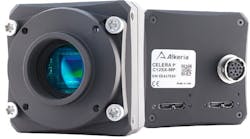
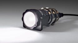
The system, which has been tested on a wide-span timber roof structure at the Staffelsee high school in Murnau, Germany, uses four mvBlueCOUGAR-X Gigabit Ethernet cameras from Matrix Vision (Oppenweiler, Germany;www.matrix-vision.com) each of which is mounted on the four main joists of the building. A series of three measurement LEDs, operating in the near IR spectrum with a wavelength of 850nm were then placed at distances of 7.5, 15, 22.5mm from the camera while a reference LED was located 30m from the camera. This reference LED was used to compensate for any errors that may occur due to unintentional camera movement.
To acquire accurate reference measurements, a Model DLS-B15 laser distance gauge from Dimetix (Herisau, Switzerland;www.dimetix.com) with a measuring range from 0.05-500m was interfaced to the system's host computer and synchronized with the vision system. Movement of the beam can then be determined by calculating the relative displacement between the measurement LEDs and the reference LED.
To calculate this movement, images from each of the four cameras was first transferred to a host PC for image processing. To separate the LED illumination from the background, the images were first thresholded and masking applied to limit the effects of any sunlight reflection. Connected component analysis was then used to separate the pixels into connected regions and blob analysis used to calculate the center of gravity of each LED region. Pixel coordinates were then transformed into real-world coordinates, the conversion factor of which was determined by the distance between the LEDs and the camera. This software was written in C# using the nGI image processing library from Impuls Imaging.
In addition to the cameras, LEDs and laser distance gauge, a weather station from Sommer Messtechnik (Koblach, Austria;www.sommer.at) was installed on the roof of the building to provide a correlation between measured roof deformation and climate conditions. Information such as air temperature, humidity, snow load, wind direction and velocity from this station was then captured by the system's data logger and transferred to the measurement system's host CPU.
Using a GUI, an operator can then display and control data from the cameras, laser distance gauge and weather station and store the results in an SQL database (Figure 1, page 16). To test the bending stiffness of the timber roof structure at the high school, known quantities of mortar mixing tubs were placed on the roof by Murnau's voluntary fire department, producing a known uniform surface load. After measuring the sag produced by the weight and comparing this value with statistically determined values, the bending stiffness of the joint was determined.
Based on these data, critical deformation values were determined to provide the operator an indication of when the roof should be inspected. While the prototype system cannot replace a specialist's assessment of the weight carrying capability of such structures, it does provide additional data that can determine safe operating conditions.