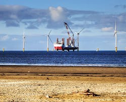
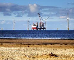
A vision-based tracking system has been deployed in the offshore wind industry to ensure the integrity of welded seams in monopile manufacturing.
Bob Beattie and Jonathan Moore
First patented in 1935, the technique of Submerged Arc Welding (SAW) is still widely used in heavy industry because it enables high deposition rates and gives good quality results in welding thick material. For example, it is well suited to the longitudinal and circumferential welds required in the manufacture of large cylindrical structures.
One of the more recent uses of the SAW welding technique has been in the manufacture of the thick tubes known as monopiles for the offshore wind industry. Once constructed, the long tubular structures, which can be 100m long, are pile driven through clay into the seabed, after which a transition piece is mounted on the top of the monopile enabling a turbine tower and the rest of the turbine superstructure to be bolted onto it.
In the monopile manufacturing process at the Netherlands-based Sif Group (Roermond, Netherlands; www.sif-group.com), a single monopile is built up from smaller 4m long cylindrical segments known as cans. Each can is produced by rolling a large rectangular plate, up to 120mm thick, into a cylinder. An automated welding system then welds the inside beveled edges of the plates together longitudinally. The can is then rotated though 180° and the outer edges of the plate are milled out before they too are welded automatically.
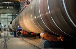
The complete monopile is then assembled, "growing" it by welding one can at a time via an internal circumferential welding process on a machine known as a "crocodile", which uses a combination of simultaneous hydraulic clamping and welding to make sure that the cans are correctly aligned. Finally, the outside circumferential seams of the assembled monopile are welded to complete the process (Figure 1).
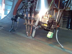
The SAW technique used in the manufacture of monopiles at the Sif Group involves the formation of an electrical arc between continuously fed wire electrodes and the two surfaces to be welded together. The weld is formed by the arc melting the surfaces and the wire. A blanket of powdered flux is deposited over the surfaces during the process which protects the molten material from the atmosphere and adds alloying elements to the molten weld pool.
In an ideal situation, the path of the weld would be perfectly repeatable, the angle of the bevel on the edges of the two steel plates to be welded to form the can would be identical, and the joints themselves would be perfectly aligned. In such a case, the location and the volume of the weld to be deposited along the length of each cylindrical can would be exactly the same. However, in practice this is never the case, since the position of the weld depends on many factors; the bevel angles of the plates may vary, and the joints themselves may be slightly misaligned.
Imaging weld joints
Due to these variations in weld shape and position, it is important that each automatic welding machine can adapt to the varying geometric properties of the joint as the machine makes each weld. To enable the various internal and external longitudinal and circumferential machines to do so, Meta Vision Systems (Oxford, UK; www.meta-mvs.com)-a company formed in 1984 as a spin out from a research project at Oxford University-has developed a vision-based system specifically for the application.
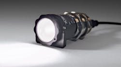
The system uses a custom-built Digital Laser Scanner (DLS) which is mounted directly on the welding head and uses a scanning laser spot to exploit the well-known triangulation principle of range data acquisition. The scanning spot type laser sensor has important advantages over the more conventional laser stripe sensor for large weld joints, since it provides very good image quality even with deep steep-sided weld joints and can operate with immunity to surface conditions.
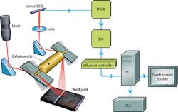
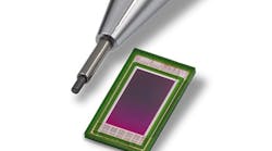
In use, a laser spot generated by the sensor scans across the steel sections to be welded a set distance, typically 100-300 mm, ahead of the welding torch, just in front of the blanket of flux under which the welding arc is submerged. To do so, the light from the laser is projected on to a galvanometer which sweeps the spot of light across the surface of the sections to be welded. The reflection from the joint is then de-scanned by the same galvanometer and focused by a lens onto a linear 2048 element CCD imager from Teledyne DALSA (Waterloo, ON, Canada; www.teledynedalsa.com) inside the sensor (Figure 2).
The distance from the welded surface to the sensor determines the point at which the spot of reflected light is formed on the imager. Hence by detecting the location of the imaged spot on the sensor, and the angle between the laser and the sensor, the distance from the surface of the joint to the sensor can be calculated for each point across the scan.
Data processing
The data from the CCD imager is processed inside the DLS by a Cyclone FPGA from Altera (San Jose, CA, USA; www.altera.com) and a TMS320 DSP from Texas Instruments (Dallas, TX, USA; www.ti.com) that work together to transform the raw image data captured by the CCD into two-dimensional profiles of the surface of the welded joints. These are then transferred over an Ethernet interface to a PC (Figure 3).
As the scattered laser light from a specific point on the surface is focused onto the CCD, a sequence of analog voltages is created that represent the distribution of laser light at each pixel on the sensor. Effectively, each laser spot forms a Gaussian-like profile on the imager from which the peak intensity must be determined at any given time to enable the sensor to make an accurate distance measurement to the surface.
To do so, the analog data from the CCD is converted to a digital bit stream and processed in real time by the FPGA which performs a filtering operation on the data to determine the center of the laser spot on the imager. The process is performed for each set of analog voltages produced by the sensor as the galvanometer sweeps the laser across the surface to be welded.
Having determined the center of each spot on the imager, the data is then sorted by the DSP to produce a two-dimensional profile of the surface. To do so, the DSP takes the polar coordinate data from the FPGA and, using a transformation matrix, converts the data into rectangular coordinate data which are expressed as a profile of vertical and horizontal points. However, since the data is, at this point, uncalibrated height data, the DSP also has to mathematically transform the data into real world coordinates. To do so, the data is transformed by a mathematical matrix previously derived during calibration of the system.
By calculating the two-dimensional profile of the welded joint in the DLS, the data can then be reliably transmitted under control of the DSP over an Ethernet connection to an industrial PC for further processing, even when the sensor is mounted in an electrically-noisy SAW environment.
Automatic control
The profile data from the sensor is processed by the PC using proprietary software developed at Meta Vision Systems to control the operation of the automatic welding head, typically a tandem or triple SAW head from Esab (Gothenburg, Sweden; www.esab.com) or Lincoln Electric (Cleveland, OH, USA; www.lincolnelectric.com), and to drive a touch screen interface that can be used by an operator to both visualize and control the welding process.
Due to the thickness of the steel plates used to manufacture the cans, it is not possible for the beveled edges of the plates to be fully welded together in one pass. Instead, the robotic welder makes a number of passes over the sections to be joined in a process known as multi-pass welding which involves depositing one weld bead in each of many weld runs.
To enable the welding system to accurately deposit beads in the first pass deep in the bottom of the joint, known as the root pass, as well as subsequent beads deposited in further fill passes, the PC identifies key points on the real world cross sectional profiles of the seam and measures their position as the scanner moves relative to the seam. The software in the PC can also calculate key parameters such as the cross sectional area of the joint.
Once such features have been determined, the data is analyzed to determine where the welding wire needs to be placed in the weld seam to create an effective weld. To do so, the software in the PC calculates the trajectory that the welding head needs to follow as it moves to the point at which the seam was scanned. The trajectory data is passed to a CompactLogix PLC from Allen-Bradley (Milwaukee, WI, USA; www.ab.rockwellautomation.com) that is interfaced to two linear servo slides that support and move the welding head to its optimal horizontal and vertical positions during the welding process.
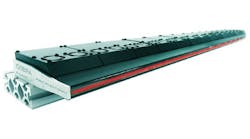
Meta's design of heavy duty and extra heavy duty linear slides use a robust steel frame, within which the carriage is mounted on four linear bearings on two parallel rails driven by a precision ball screw with a recirculating ball bearing nut. Motion is provided by an AC servomotor with integral high resolution encoder from Yaskawa Electric (Kitakyushu, Japan; www.yaskawa.co.jp) driving the ballscrew via a reduction gearbox from Shimpo (Kyoto, Japan; www.nidec-shimpo.co.jp).
In addition to calculating the target position where the welding wire needs to be placed, the PC software calculates how much material will need to be deposited in the seam from the analysis of volumetric data. From that analysis, the PLC is instructed to modify the rate at which the consumable electrode wire is fed into the joint via a servo motor as well as the rate at which the welding head moves along the seam. This type of "adaptive fill" has also proven to be very useful in other applications, such as welding earthquake-proof beams, where the joint volume intentionally changes dramatically to achieve the final beam properties.
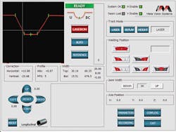
The Windows-based touch screen interface running on the PC enables the operator to observe the profile of the joints and monitor the effectiveness of the system during the multi-pass welding process. To do so, the screen displays the profile of the seam that the robot is currently welding and the key numerical characteristics of the seam (such as its height and width) and the profile of the weld beads that are to be laid down during subsequent operations (Figure 4).
Over the past ten years, several Meta Vision Systems control systems have been deployed at the Sif Group where they have been used to control and optimize the welding process used in monopile manufacturing. Today, the company is currently deploying such systems to build monopiles for Project Gemini, a new 600MW offshore wind farm in the Dutch North Sea. These monopiles will feature a length of 65m, a bottom diameter of 7m and a weight of 850 tons. The construction of the wind farm will start next year and the wind farm is planned be operative by the summer of 2017.
Bob Beattie, Managing Director, and Jonathan Moore, Technical Director, Meta Vision Systems (Oxford, UK; www.meta-mvs.com)
Companies mentioned
Allen-Bradley
Rockwell Automation
Milwaukee, WI, USA
www.ab.rockwellautomation.com
Altera
San Jose, CA, USA
www.altera.com
Esab
Gothenburg, Sweden
www.esab.com
Lincoln Electric
Cleveland, OH, USA
www.lincolnelectric.com
Meta Vision Systems
Oxford, UK
www.meta-mvs.com
Nidec-Shimpo
Kyoto, Japan
www.nidec-shimpo.co.jp
Sif Group
Roermond, Netherlands
www.sif-group.com
Teledyne DALSA
Waterloo, ON, Canada
www.teledynedalsa.com
Texas Instruments
Dallas, TX, USA
www.ti.com
Yaskawa Electric
Kitakyushu, Japan
www.yaskawa.co.jp
