Industrial Automation: Robots and vision team-up for pipe welding
By adding vision to their robotic welding systems, manufacturers can ensure that, even in harsh environments, improved weld quality will be obtained while at the same time production costs will be lowered. In such systems, structured light projected over the joint to be welded is used to determine the location of the joint and this information used to guide the position of a laser welding torch attached to the end-effector or a robot. By employing vision, any positional inaccuracy in the robot manipulator and part fixture variations can be compensated, thus improving the quality of the final weld.
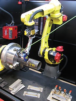
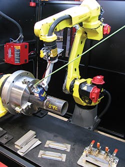
In a demonstration at this year's Automate trade show and conference, held in Chicago, Lincoln Electric (Cleveland, OH, USA; www.lincolnelectric.com) showed its System 5 advanced process work cell for automated welding applications that uses a vision-guided robot to perform this task. In the demonstration, the capabilities of the robot and vision system were shown using a FANUC ARC Mate 100iC series six-axis, servo-driven robot from Fanuc Robotics America (Rochester Hills, MI, USA; www.fanucrobotics.com).
In operation, the end-effector of the robot was shown picking two structured light-based systems from a rack, performing a scan of the part to be welded and then picking a MIG welding torch to perform a simulated welding task on a rotating part.
"In a typical system however," says Mark Fisher, Field Applications Technologist with Lincoln Electric, "both the sensor and the welding torch would both be mounted to the end-effector of the robot. To perform the task of scanning the part, an SLS ARC sensor from Meta Vision Systems (Saint-Laurent, QC, Canada; www.meta-mvs.com) was used. The option of using a DIGI-LAS/MDL 3D laser vision system from Servo-Robot (St-Bruno, QC, Canada; www.www.servorobot.com) is also available. Either system can be integrated into Lincoln Electric Automation Solution systems.
"To perform joint tracking requires capturing an image just ahead of here the weld is to be performed," says Fisher, "using data from these image sensors, the robot's path can then be dynamically adjusted to keep the welding wire positioned correctly in the joint."
Before this can be accomplished, however, the robot must be trained to locate the position of the weld. To perform this task, an operator uses a teach pendant interfaced to a Fanuc R-30iB robot controller to program the scanning path and monitor and control the arc welding functions. After programming, the robot can be positioned over the part to be welded.
Once in operation, structured laser light is then projected ahead of the weld and the reflected structured light used to compute a 3D map of the to-be welded joint. This 3D image is then used to compensate for robot trajectory shifts and allows for adaptive control of the robot. This allows real-time movement and manipulation of the robot, adjusting for the part being welded.
To perform this welding the System 5 work cell employs Lincoln Electric's its Power Wave S500 welder and Cool Arc 55 water cooler. Although set-up as a MIG system, the system is also suitable for shielded metal arc and tungsten inert gas (TIG) welding.

