Industrial Automation: Smart cameras inspect automotive sub-assemblies
Injection-molded plastic parts constitute many sub-assemblies used in automotive manufacturing. After manufacturing, these parts are then fitted with clips to ensure that the sub-assemblies can be correctly mounted within the automobile. While this process is accomplished automatically, the final sub-assembly must be inspected to ensure that the molded locking tabs and locking clips are in place.
When contacted by a large automobile manufacturer to perform this task for an automotive speaker grill, TA Systems (Rochester Hills, MI, USA; www.ta-systems.com), a large automotive systems integrator, turned to the Vision and Traceability Group of McNaughton-McKay Electric Company (Madison Heights, MI, USA; www.mc-mc.com) to evaluate whether this task could be automated.
"At the automotive manufacturer," says Ryan Gribeck, Systems Engineer with McNaughton-McKay Electric Company, "clips are robotically placed and it was necessary to develop a system that could be placed within the confines of the robotic cell."
In this way, parts that were deemed to have passed the inspection could be automatically removed by the robot and placed into a bin for further processing. Should a part fail, the operator can then be flagged to remove the part for rework.
To perform the inspection task, two L300-625-W 12in x 3in linear red wide-angle LED lights from Smart Vision Lights (Muskegon, MI, USA; www.smartvisionlights.com) were mounted at 45o angles approximately 66in from the part. "Since the parts are completely black," says Gribeck, "the use of high-brightness dispersed off-axis illumination reduced the amount of reflected light from the part."
Rather than choose to image the part with a single high-resolution camera, two In-Sight 7020 smart cameras from Cognex (Natick, MA, USA; www.cognex.com) were chosen for the task. While one camera was mounted with a 12.5mm Fujinon lens from Fujifilm (Minato, Tokyo, Japan; www.fujifilmusa.com) and a BP635-25.5 light red bandpass filter from Midwest Optical Systems Palatine, IL, USA; www.midopt.com), the second used a 25mm Fujinon lens, also fitted with a BP635-25.5 filter.
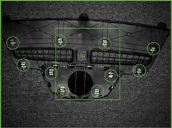
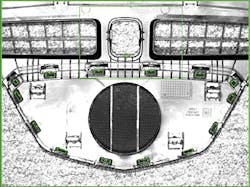
The camera with the 12.5mm lens was used to capture an image of the complete part and all the associated clips. The camera fitted with the 25mm lens was then used to capture just the area of the part where the locking tabs are placed. This resulted in a resolution of approximately 35 pixel/in (for the full image) and a 70 pixel/in resolution (for the sub-image).
"Because the LED lights used in the system were so bright," says Gribeck, "it was necessary to trigger the lights and camera simultaneously to minimize operator fatigue." Once the part was properly fixtured, the lighting and cameras were triggered via PLC. After images are captured they are processed by In-Sight software running in both of the smart cameras.
To setup the camera, Cognex's In-Sight software running on a PC was used to configure the machine vision algorithms required. Once finalized, this was then downloaded to the smart cameras.
To determine whether the clips are present, Cognex's pattern matching algorithm was used to determine the location of the part. Once determined, regions of interest (ROIs) were defined around the location of each of the clips. Cognex blob tools were then used to look for white blobs within the ROIs to determine if a clip was present.
To identify whether the tabs were properly formed, the image from the second camera is thresholded to highlight the tabs and pattern algorithms were again used to determine whether a tab is crimped or in an upright position. Pass/fail information and whether any tab or clip has failed inspection is then transferred over the camera's Ethernet interface to a Control Logix PLC from Allen-Bradley (Milwaukee, WI, USA; www.ab.rockwellautomation.com). Should the part pass inspection it is then automatically removed by the 2000IA/IQ robot from Fanuc (Hoffman Estates, IL, USA; www.fanucamerica.com) located in the workcell. Should a part fail inspection, the operator is alerted to remove the part for further rework.


