")
Tire manufacturer Steelastic (Akron, OH, USA; www.steelastic.com), a supplier of flexible solutions for the tire industry, has implemented DS1101 3D laser displacement scanners from Cognex (Natick, MA, USA; www.cognex.com) into an automated and traceable machine vision system for the inspection and measurement of apexed beads.
A vital component of all tires, the bead is a bundle of wires in each sidewall that secures the tire to the wheel.1 The rubber bead apex envelops the bead to facilitate its incorporation into the sidewall. It also plays a key role in the ride and handling characteristics of the tire (Figure 1). 2
A previous inspection system used a localized system that looks at only the top side of the splice, where the start and the finish ends of the apex join, despite the splice being the most susceptible location for defects. This system also missed many other features and defects. Top and bottom inspection allows the Steelastic 360-Degree Bead Apex Inspection System (patent pending) to catch defects that are harder to see on only one side.
The system scans the circular bead apex and checks for a variety of defects, including bare bead/bead integrity, foreign objects, heavy and open stitches, and dog-ears. The system also measures the thickness of the rubber and splice height to ±0.150 mm and ±0.125 mm, respectively.

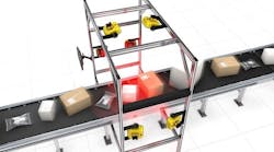
The bead apex is robotically loaded into one of two stations on the inspection system, both of which have rollers that capture, center, and rotate the apex over its full circumference for complete and simultaneous 360-degree inspection of both sides of the part (Figure 2).
Steelastic uses Cognex Designer, a flexible application development environment, for ease of application configuration. Cognex Designer provides both 2D and 3D analysis tools for surface and feature measurement as well as feature segmentation for defects.
The inspection system also archives images and supplies an audit trail of all inspections and parts. Steelastic uses Cognex Connect to enable better communication with factory-floor protocols.
At the heart of each station in the inspection system are two Cognex laser displacement sensors in an opposing-view orientation. In this configuration, the sensors face each other, with the part in the middle and the laser lines aligned with each other. Both sides of the part are inspected simultaneously at the same position on the circumference of the apex ring. This configuration allows Steelastic to use fewer scanners, resulting in a more compact system and 100% inspection of the bead apex.
 showing typical defects—such as dog-ears, open splices, and splice bulges—and related measurements. Color has been added to the images to help show height variation.")
The laser displacement systems deliver a continuous, spatially aligned height image of the top and bottom surfaces. The difference between the two related height measurements is used to calculate the thickness of the apex at a high resolution around the entire ring. Along with the continuous thickness measurement, the systems create a 3D profile that is used to check for missing material, find defects, and measure features such as part width, splice position, and splice overlap (Figure 3).
Cognex DS laser displacement sensors use laser line triangulation imaging to create a high-resolution range image that shows the height of the surface of the object in the field of view. Scanning frequencies of up to 18 kHz and 1024 horizontal profile points deliver measurement resolution as small as 0.005 mm. A Cognex VC5 vision controller comes with an operator interface and displays the results and images. The controller also offers configuration and setup and recipe creation and selection while data logging all measured values to an SQLite database.
If a fault is detected, a robot will move it to another location, such as a reject conveyor, where it can be repaired or scrapped depending on the defect.
The new inspection system is in beta testing to validate multiple beads run for accuracy and repeatability.
Resources
1. U.S. Tire Manufacturers Association
2. Steve LaFerre, “Back to Basics: Part 1: Beads and Sidewalls and What They Add to Performance,” Tire Review, February 3, 2005.
Figure SEQ Figure \* ARABIC 1. A bead apex component prior to incorporation in a finished tire. (Photos courtesy of Steelastic.)
Figure SEQ Figure \* ARABIC 2. Top view of opposed laser scanning of the apex surface.
Figure SEQ Figure \* ARABIC 3. 3D range images (top and bottom pairs) showing typical defects—such as dog-ears, open splices, and splice bulges— and related measurements. Color has been added to the images to help show height variation.