Mike Fussell
Welcome to Part 2 of a three-part series covering the essentials of motion control for vision professionals. Part 1 covered the types of motion, the advantages of devices with integrated drivers and controllers, and their key specifications. Part 2 builds on those topics to help you optimize your vision system performance and cost by selecting devices with the most suitable motors, encoders, bearings, and drives for your application.
Motor Types
Motors are the foundation of all motion control devices. There are two main classes of motor: rotary motors, which include stepper and servo motors, that require drive mechanics to convert their rotary motion into linear motion and linear motors that produce linear motion directly with no additional drive mechanics.
. As the electromagnets are sequentially energized (B), teeth on the rotor are pulled into alignment with teeth on the energized electromagnet (C), while teeth on adjacent electromagnets are pulled out of alignment, setting the motor up for the next step. (Drawings courtesy of Zaber Technologies.)")
Stepper Motors
Stepper motors generate rotary motion using electromagnets arranged in opposing groups around a toothed permanent magnet rotor. When one group of teeth is aligned with the closest electromagnet, the adjacent teeth are partially aligned with the electromagnets near them. By energizing the electromagnets sequentially, the teeth of the rotor will step from aligning with one group of magnets to the next.
The more teeth a stepper motor has, the smaller its movement steps. Stepper motor controllers like those integrated into Zaber’s (Vancouver, BC, Canada; www.zaber.com) X-series motion control devices can enable microstepping by partially energizing several groups of electromagnets simultaneously, moving the rotor to intermediate position steps.
Stepper motors deliver excellent torque at low speeds which enables them to hold loads in a static position. This makes them ideal for stabilizing and positioning cameras on unmanned aerial systems (UAS) as they can hold cameras and optics in place against the force of gravity and the acceleration of the UAS as it moves. By producing high torque at low speeds, stepper motors can accelerate loads quickly. This is useful for applications like imaging of biological samples in microplates that require the sample to be rapidly moved between positions in a sequence of small and precise movements. The small, rapid, and repeated movements of a 3D printer nozzle are also very well suited to stepper motor drives. At high speeds, the maximum torque of stepper motors falls off (Figure 4) because of the high number of magnetic field changes per revolution.
. As the electromagnets are sequentially energized (B), they pull permanent magnets on the rotor into alignment with electromagnets fixed to the motor body.")
Servo Motors
Servo motors generate rotary motion with electromagnets arranged around a set of permanent magnets attached to the rotating shaft. The electromagnets engage sequentially, pulling the permanent magnets in one direction. To operate efficiently and generate maximum force across a broad range of speeds, servo motors require additional electronics, increasing their cost relative to stepper motors.
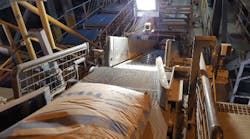
Servo motors produce constant torque across their speed range, enabling them to deliver high torque at high speeds. This makes them ideal for driving high-speed continuous flow processes like printing and thin film production. The high-speed tooling including routers and drills found in some industrial vision-guided automated manufacturing systems rely on servo motors. When moving a light load such as a mirror for a laser beam profiling scanner or LIDAR, servo motors generate less heat than stepper motors making them useful for space-constrained embedded systems like mobile robotics where managing heat from cameras and processors is frequently a concern.
. As the electromagnets on the mover are sequentially energized (B), they are pulled into alignment with permanent magnets fixed to the stator.")
Linear Motors
Linear motors use a line of sequentially energized electromagnets to force a mover over a track of permanent magnets. They produce linear motion directly without requiring any additional mechanical components. Eliminating these drive components eliminates the main sources of friction and backlash. This enables linear motors to accelerate extremely quickly and achieve very high accuracy and repeatability. Linear motors are more expensive than rotary motors, but their combination of high accuracy, high acceleration, and virtually unlimited service lives makes them well worth the investment. They reduce maintenance and unscheduled down time costs while increasing throughput.
When unpowered, linear motor devices can move freely. They must remain powered to hold a load in place. When using a linear motor in a vertical configuration, such as for an auto-focus system, a counterbalance like those offered with linear motor devices like the Zaber X-LDA and X-LDM will offset the force of gravity. This will reduce the power consumption of the system and reduce the heat it generates. The combination of high accuracy and thrust has made linear motors the actuator of choice for many new high-performance consumer camera lenses from Canon, Sony, and Nikon. The rapid-acceleration linear motors can distort larger liquid lenses. Reducing their acceleration will mitigate this effect.
The high accuracy and repeatability of linear motors makes them ideal for PCB population and inspection which requires very high repeatability for accurate positioning of components, and where the requirement for high throughput demands many short, fast moves that would cause rapid wear of the components in a rotary-motor-driven device. The nanometer-level minimum incremental move of quality linear motors can deliver the fine control necessary for semiconductor packaging. These systems require extremely high accuracy and repeatability to ensure stacked chiplets are aligned with the correct interconnects.

Encoders
Encoders are sensors that detect mechanical movement. There are many different types of encoders. Optical encoders are the best for most vision system applications because of their high resolution, repeatability, and accuracy. Encoders enable tight synchronization between target movement and image acquisition. A digital output signal driven from an encoder will enable accurate high-speed triggering of line scan cameras. Synchronizing line scan camera triggering to an encoder signal eliminates distortion caused by fluctuations in the target's movement speed. A camera trigger signal directly driven by the system's movement will automatically compensate for variations in speed, while a camera operating at a fixed line rate will not.
Motor encoders measure the rotation of the drive motor. They do not measure the absolute position of the carriage along its travel, so imperfections in the mechanical conversion of motor rotation to carriage position will affect the accuracy of the reported position. Motor encoders can detect if a stepper motor has slipped or stalled. If a high-speed optical filter wheel in a multispectral imaging system operating near the limits of its drive motor stalled, a motor encoder would allow the system to detect the issue and recover automatically (for example, reducing the speed) without loss of position reference.
Direct encoders measure the absolute position of linear stages and the angle of rotary stages. Direct position measurement means the accuracy of the reported position will not be impacted by mechanical imperfections in the conversion of motor rotation to the final carriage position. Motor controllers can use this data to approach the target position, improving stage accuracy and repeatability. Zaber applies interferometer-based calibration to correct for small offsets between encoder and absolute position. This compensation is applied by Zaber devices’ integrated controller, simplifying the design of precision optical and metrology systems.
Direct encoders with resolutions of 1 nm can help maximize the throughput of semiconductor wafer and packaging inspection systems that rely on high-magnification optics. High-resolution encoders enable device controllers to measure system vibrations and trigger cameras immediately upon settling below a target vibration threshold rather than waiting for an arbitrary settling time, which would add an unnecessary delay and reduce system throughput.
 move smoothly in one axis while their bearing orientation gives them excellent stiffness in all other directions.")
Bearing Mechanics
Bearings ensure moving parts travel efficiently and smoothly in one axis while constraining them to prevent unwanted movement on all other axes. Incorrect bearing selection may result in friction and jerking movements of inspection targets, causing unwanted distortion of line scan images. Inadequate bearing stiffness could result in blurring of long-exposure images due to vibrations. Appropriate bearing selection could eliminate the need for more expensive, wider aperture optics or higher power lighting.

Plain Bearings
Plain bearings are the simplest form of bearing. They use low-friction sliding elements running on smooth surfaces that constrain motion to just the desired axis. The simplicity of plain bearings keeps them lightweight, compact, and inexpensive. Dry running polymer plain bearings are chemically inert and self-lubricating, making them virtually maintenance-free. Plain bearings’ simplicity enables easy customization. Simple diverters in a quality inspection system may use plain bearings.
While low-friction materials are used in plain bearings, their sliding motion is still much higher friction than the rolling motion of ball or roller bearings. This makes plain bearings a poor choice for applications like vision-guided gemstone cutting where fine, smooth and highly repeatable movements are required. The higher friction of plain bearings may necessitate the use of more powerful and more expensive motors than would be required from more expensive, but lower friction, ball or roller bearings. This friction can cause them to bind under cantilevered loading so if cameras are moved on plain bearings, mounting them close to the bearing is recommended. Plain bearings cannot be preloaded to the extent that ball or roller bearings can be, resulting in less effective constraint of unwanted movement. A lightweight camera and S-Mount lens may perform well on a plain bearing system, however a large 10GigE camera and high-quality F-Mount lens may cause the bearing to bind. Excessive heat from friction can quickly degrade plain bearings if they are pushed beyond their speed and load design limits.

Recirculating Bearings
The rolling motion of ball bearings makes them much lower friction than the sliding motion of plain bearings. By containing ball bearings within a closed path, they will recirculate around the load-bearing surface. This design provides “infinite travel” if there is a hardened steel raceway for the recirculating bearing block to travel along. Recirculating bearings would be ideal for a cartesian robot performing vision-guided adhesive application in automotive production. Integrating recirculating bearings into the moving applicator and guidance head would eliminate the need for bearings along full length of the system’s travel, reducing its cost.
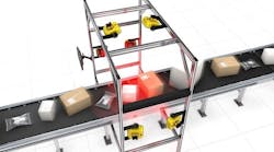
With much lower friction than plain bearings, recirculating ball bearing devices are better suited for high-speed motion. They can also provide much greater accuracy and repeatability than devices relying on plain bearings. These properties make recirculating bearings ideal for use in long-travel systems supported by gantries such as those for inspecting randomly oriented parts on a conveyor and in the inspection of welds.
As bearings circulate, they move in and out of the raceway. Minute differences in ball bearing size and surface imperfections in the raceway can result in acoustic noise and vibration of the carriage. Recirculating bearings require lubrication to roll smoothly. This necessitates periodic maintenance, adding to their lifetime cost.
Crossed-Roller Bearings
Crossed-roller bearings combine low friction in their axis of movement with very high stiffness in all other axes. Their friction force is extremely consistent and predictable, making them a good choice for metrology applications where velocity stability, high accuracy and high repeatability are required. They are ideal for inspection systems using high-magnification optics for mobile phone OLED display inspection where returning to saved positions with micrometer-level repeatability is essential to guarantee that key inspection target features are imaged consistently and reliably.
Crossed roller bearings’ excellent rigidity minimizes vibrations to achieve rapid settling times between movements. Faster settling times translate into higher throughput, particularly with high magnification optics where even small vibrations can result in blurred images. Roller bearings distribute their loads over a larger area than ball bearings, making them better for supporting heavy loads or for working at higher thrust. These bearings are commonly used on a wide range of robots to provide smooth, efficient, and accurate movement while lifting large workpieces like engine blocks or aircraft parts. The mechanical performance of crossed roller bearings demands high-precision manufacturing, which increases their cost relative to ball bearing designs.

Drive Mechanics
Many vision systems are based on Cartesian robots that combine several axes of linear motion to move targets and cameras relative to each other. Linear X and Y axes may be combined move a camera in a plane over the cylinder heads of an engine block to inspect the surface machining. To produce this linear motion, the rotary motion of stepper and servo motors must be converted into linear motion by a drive mechanism. The type of drive mechanics used by a motion control device will determine the applications it is suited for and its cost.
Lead Screw
In lead-screw-driven-devices, a rotating screw drives a lead nut fixed into the carriage, moving it along its travel. The basic lead screw design is extremely versatile, allowing it to be optimized for specific applications. Lead screws are available in a wide range of sizes, pitches, manufacturing tolerances, and materials depending on your requirements for travel, speed, repeatability, and chemical resistance. Lead screws are very compact, making them ideal for integration into space-constrained designs. Self-locking lead-screw devices cannot be easily back-driven and will remain in place when unpowered. This makes them excellent for lifting vertical loads, as once their load has been positioned, it will stay in place. They are used in many smaller-volume and higher-precision additive manufacturing systems.
The accuracy and repeatability of lead screws depends on the precision of their manufacturing and their length. Higher-precision lead screws are more expensive. A lead screw’s accuracy decreases proportionally to its length, while its repeatability is independent of its length.
The threads of the lead screw and the lead nut slide across each other. As seen with plain bearings, this sliding movement is inherently higher friction than the rolling motion found in other drive mechanisms. Higher friction requires more torque and larger, more expensive motors to drive. Heat can build up quickly if the recommended limit of speed and load is exceeded, leading to increased wear. Accuracy is reduced, and backlash is increased as drive components wear over time. Wear is accelerated by extended operation at maximum speed, so while an inexpensive lead-screw drive may yield a lower upfront system cost, the increased long-term costs due to maintenance and process drift reducing yields may outweigh the short-term savings . Lead screws pair well with stepper motors as their performance is best at lower speeds. Stepper-motor-driven lead screw stages, like the Zaber X-LSM series, are versatile and cost effective, delivering a good balance of accuracy, repeatability, and speed. This makes them a popular choice for prototyping vision systems and in research and development for structured light and multicamera depth sensing solutions for robot guidance, as camera positioning can be quicky and accurately adjusted remotely.
Ball Screw
A ball-screw-drive mechanism combines the basic design of a lead screw with a recirculating ball bearing path. Unlike a lead screw that slides over its lead nut, ball screws use ball bearings that roll, greatly reducing friction. The increased mechanical complexity of ball screws relative to lead screws makes them more expensive and less easily customized. However, their lower friction makes them much better suited for high speed and high throughput applications like SMT pick-and-place machines. Lower friction also enables ball screws to make smaller incremental movements than lead screws, making them well suited for driving the hexapod platforms used to position aspherical lenses during inspection.
Ball screws are not self-locking and will not remain in place when unpowered. They require a brake to hold a vertical load. Ball screws require more maintenance than lead screws and must be lubricated to function correctly. This makes them more sensitive to environmental contaminants and necessitates ingress protection in dusty or dirty environments. Correctly maintained ball screws have much longer service lives than lead screws. Their lifespans are also much more predictable as they are much less impacted by speed and load compared to lead screws.
Belt Drive
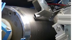
Belt drives are widely used in many industrial applications as they are cost-effective solutions for moving light loads at high speeds over long distances. These systems generally use a toothed polyurethane timing belt reinforced with steel, aramid, or glass fibers and are driven by either a stepper or servo motor. Belt-drive systems have low friction and high mechanical efficiency, enabling them to be driven by smaller, less expensive motors. These systems are not self-locking and can be easily back-driven. For vertical movements, such as camera positioning on passport control kiosks, a brake may be required to hold the camera at the desired height. Belt drives are ideal for gantry-mounted vision systems tracking randomly oriented parts on fast moving conveyors including selective laser ablation of anodization on electronic device chassis parts for EMC control. Many additive manufacturing systems operate with belt drives, particularly large-volume and low-cost systems.
Belt drive systems cope well with debris like sawdust, making them ideal for many manufacturing processes. They have significantly lower maintenance requirements than ball screw systems. As they wear over time, belts stretch, reducing both the accuracy and repeatability of movements. Belt wear is not as speed-dependent as lead-screw wear is. Therefore, the service life of these devices is more predictable. Belt-drive systems can easily be customized (Figure 7) to meet specific requirements for travel, as their costs scale slowly with length. The “infinite travel” design of recirculating ball bearings pairs with belt drives and can further improve the cost-effectiveness of long travel belt drive systems.
Selecting motion control devices with the appropriate combination of motors, encoders, bearings, and drive mechanics can have a major impact on your vision system’s accuracy, throughput, reliability, and cost. Understanding the advantages and the limitations of different motion control device components, and how they can work together will help you ensure your vision systems deliver excellent performance and competitive pricing.
The final article in this three-part series provides two detailed case studies of how the motion control systems supporting an automated cell imaging system and a vision-guided laser etching system were developed.