Stuart W. Singer and Claudia Baier
Many articles have been written about how various types of optical filters can be used to improve the contrast of images. Surprisingly, there has been little written about the quality of these filters and what effect they may have in an optical system. In some imaging systems, for example, the quality of a filter can have little to no effect; in others, filter quality can significantly alter the final image obtained by the optical system.
During the manufacturing process, optical glass filters are typically ground and polished, although some are only melted and cured to shape. When the filter is of high quality, precision grinding and polishing results in less image degradation because there will be negligible transmitted wavefront error. Although manufacturing precision ground and finely polished filter glass takes time, the added cost differential is nominal in relation to the cost of the machine-vision system. The difference in the final image that results from the integration of such precision filters over those of inferior quality can be dramatic.
Understanding resolution
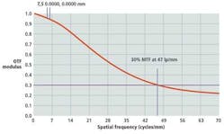
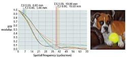
To understand how filter error affects the performance of optical systems, system developers must appreciate how the characteristics of optical systems are measured. In determining the performance of any given lens, for example, the modulation transfer function (MTF; or modulus of the optical transfer function—OTF) provides a measure of the resolving power of the lens at different spatial frequencies (see Fig. 1).
The MTF of the optical system, however, will also be dependent on other factors, such as the size of the pixels used in the imaging sensor. In Fig. 1, for example, a pixel size of 7 μm is used to illustrate the fact that the smallest object that can be resolved by such an imager is 14 μm (due to Nyquist theory). Thus, the limiting resolution at the sensor will be approximately 1000/14 or approximately 70 line pairs/mm (lp/mm). Image quality that adversely affects the image quality of the final system occurs when the MTF data at 67% of the Nyquist value (or 47 lp/mm) fall below an MTF value of 30%.
Filter error
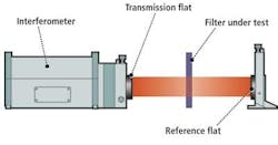
To be clear, the total system MTF is the product of the MTF of the lens, filter, camera, and electronics used to capture the image. Therefore, applying a filter to a lens can often drastically change the resolving power of the system. To calculate the filters' wavefront error, interferometers are used to illuminate the filters with a near-perfect output beam of monochromatic light known as a reference wavefront beam (see Fig. 2).
When the reference wavefront beam passes through the filter, it is perturbed by the errors in the filter. The reference flat (a near-perfect surface reflector) reflects back the perturbed beam to the interferometer. The interference pattern, or interferogram, between the filter and the reference beam can then be photographed and measured (see Fig. 3). Fringe analysis software supplied by the interferometer manufacturer is used to determine the peak-to-valley wavefront error, or the distance from the highest to the lowest point on the test wavefront relative to the reference wavefront.
Depending on the quality of the filter, this can result in a number of different interferograms that characterize the filters. For a near-perfect filter, for example, the interferogram will generate a fairly uniform fringe pattern with a 1/20th peak-to-valley wavelength error, while a poorly designed filter with a 5+ peak-to-valley wavelength error will generate a very irregular fringe pattern (see Fig. 3c).
Degradation effects
To appreciate the effects such errors may have on an optical system used in machine-vision applications, filters with varying degrees of error were applied to two standard lenses. These included a 35-mm-focal-length lens with an aperture of f/1.9 and a 100-mm-focal-length lens with an aperture of f/2.6; these are two very common lenses used in machine-vision applications.
Employing the ZEMAX optical system design program from ZEMAX (Bellevue, WA, USA; www.zemax.com), various degrees of transmitted wavefront error from the filter can be applied to the MTF plots of each lens. To accomplish this, the known reference 632.8-nm wavelength of the interferometer is used to compute the peak-to-valley wavefront error and can be converted to units (in millimeters) as base units of length and applied to the MTF of the lens.
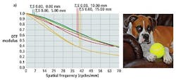
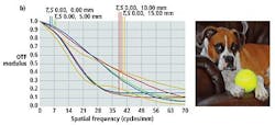
In Figs. 4–6, it is assumed that the imager used is an 8.8 × 6.6-mm, 2/3-in. sensor with a diameter of 11 mm and 7-μm pixels. Each MTF plot for the lens is calculated in terms of its on-axis performance (blue), its extreme vertical axis performance (green), its extreme horizontal performance (red), and its extreme diagonal performance (gold). As can be seen, there are two MTF plots for each, since the MTF is measured using test charts that present both tangential (T) and saggital (S) data to the lens (see "Quality Criteria of Lenses," http://bit.ly/r1l2RG). Thus, the greater the difference between these MTF plots, the larger the astigmatism of the lens.
When employing shorter (e.g., 35-mm) focal-length lenses with an aperture of f/1.9, the "footprint" of the entrance rays on the filter for each pixel is relatively small with respect to the overall filter size, making the lens less sensitive to the filter errors (see Fig. 4a). For this reason, a lower-quality filter does not produce noticeable image degradation. It takes considerable filter error before the lens is adversely affected.
If the MTF drops below the 30% minimum required value at 47 lp/mm, the optical system performance becomes compromised. It is not until the transmitted wavefront error is significant—i.e., having at least 4 wavelengths of peak-to-valley error over the entire filter—that image degradation is noticeable (see Fig. 4b).
By employing a lower-quality filter (e.g., with 4 wavelengths of peak-to-valley error) even on a lens with a small entrance pupil, image quality is compromised but not to a significant extent. This is because the lens receives only a limited segment of the perturbed rays caused by the filter error.
When a 100-mm lens is employed with a larger f-number = 2.6, the entrance pupil diameter of this lens is larger than in the 35-mm lens example. Image quality is more sensitive to filter errors. A 100-mm lens, for example, with an aperture of f/2.6 set to an optical magnification of 1.0 is significantly affected by the quality of the optical glass filter itself because the 100-mm lens—unlike the 35-mm lens—samples much more of the perturbed wavefront caused by the filter error.
For example, a 100-mm lens with a near perfect 1/20th wavelength of peak-to-valley error just meets the 30% MTF specification at 47 lp/mm as described in Fig. 3. At higher magnifications, this distortion becomes even greater and the significance of the filter quality is even more critical (see Fig. 5a). The same 100-mm lens with only 1 wavelength of peak-to-valley error reveals significant image degradation (see Fig. 5b).
At the point that the filter error reaches 1.5 wavelengths of peak-to-valley error, the effect is a dramatic loss of image quality (see Fig. 6). In this example, the lens used is highly sensitive to filter wavefront error, so even a marginal error (1.5 wavelengths of peak-to-valley error) that is expected in a filter of good to moderate quality is not good enough and will significantly affect overall image quality. Only a near-perfect-quality filter can be employed if the image quality is not to be degraded.
Choosing a filter
Optical systems that employ lenses with small apertures or short focal lengths can tolerate lower-quality filters. However, when lens apertures increase in size, the focal length is increased, sensors with pixels measuring less than 7 μm are used, or if the system requires greater magnification, then filter error influences lens performance, which degrades image quality. In such cases, a vigilant selection of filters is required to optimize image quality.
There is no question that the quality of a filter can affect the final image captured by a vision system. Unfortunately, filter manufacturers rarely provide data about the optical quality of the filters, and even when such information is requested, it is difficult to obtain. Although many vendors do not seem to either possess or wish to impart such data, parameters such as transmitted wavefront error can easily be measured using an interferometer.
By providing these details to their customers, filter vendors can help developers more optimally specify their optical systems. If this analysis is not performed prior to integrating the filter with the lens, the system developer will have to test the machine-vision system before and after employing the filter to observe any potential loss of image quality.
Stuart W. Singer is vice president of Schneider Optics (Hauppauge, NY, USA;
www.schneideroptics.com) and Claudia Baier is product line and sales manager—industrial filters at Jos. Schneider Optische Werke (Bad Kreuznach, Germany; www.schneiderkreuznach.com).


