Andrew Wilson, Editor
Applications such as robotic bin picking, object tracking and product profiling demand systems that are capable of generating three-dimensional (3D) image data. To perform such tasks a number of both passive and active techniques can be used, each of which present the developer with different price-performance tradeoffs.
While passive 3D systems such as stereo camera implementations only require ambient lighting, active lighting such as structured laser light and projected pattern-based lighting systems use external lighting sources to illuminate the object to be measured. This difference in illumination method is important since the less well-defined features an object may have, the less accurate the system will be when passive lighting is used.
This is not the case, however with active lighting systems, since a known structured light or projected light pattern light pattern is used to illuminate the object. However, using active lighting can result in measurement inaccuracies, especially when the edge of objects or objects with varying surface finishes need to be imaged.
Passive imaging
One of the most commonly used passive 3D systems is based on stereo imaging in which two cameras are used to capture two separate images of a scene from two different viewpoints. In such systems, the location and optical parameters of each separate camera must be calibrated so that triangulation methods can be used to determine the correspondence between pixels in each image.
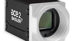
Relative depth of points in the scene can then be computed since the depth of each point is inversely proportional to the difference in the distance of the corresponding points and their camera centers. This can be then used to generate a disparity map that visually provides 3D information. Because the positional and optical parameters of two separate cameras must be accurately calibrated, many products such as the Bumblebee series from Point Grey (Richmond, BC, Canada; www.ptgrey.com) use dual cameras that are pre-calibrated, relieving the systems developer of such tasks (Figure 1).

Disparity values obtained from stereo image pairs are directly proportional to the distance the cameras are apart and inversely proportional to the distance an object is away from the two cameras. Thus, in integrated stereo systems, increased disparity accuracy cannot be obtained by moving the cameras further apart but only by moving the dual camera system closer to the object being examined.
Motion stereo
While such calibrated systems are used in many vision-guided robotics applications, other methods that use single camera implementations can be used. In such motion stereo systems, a single camera is mounted on a robot and takes images from two or more locations. Because the baseline between camera views can be generally longer than preconfigured dual camera stereo systems, the disparity accuracy can be increased. However, such systems require that any robotic camera positioning errors must be minimized since this will affect the accuracy of the 3D data obtained.
More than five years ago, Motoman (Miamisburg, OH, USA; www.motoman.com) demonstrated how 3D information could be obtained by using a single camera mounted to the company's seven-axis, in-line SIA20 robot. Known as MotoSight 3D, the PC-based system was used to locate randomly stacked parts to be picked up and placed accurately into a press or machine tool (see "Robot Guidance," Vision Systems Design, November 2008; http://bit.ly/1pUVMUG).
Other manufacturers, such as Robotic Vision Technology (Bloomfield Hills, MI; http://roboticvisiontech.com) also use this same concept to locate parts in 3D space. In the company's eVisionFactory software, an AutoTrain feature can be used to automatically move a robot and camera through multiple image positions as it measures features of the part being imaged. This data can then be used to provide location and orientation information without the need for pre-loaded CAD data models of the part to be known.
Such motion stereo vision can also be applied to mobile robots as has been recently demonstrated by Stephen Karungaru and his colleagues at the University of Tokushima (Tokushima, Japan; www.tokushima-u.ac.jp). In their implementation, a mobile robot equipped with a single camera is used to compute the location of a target object. A simple-to-use interface controls the robot's actions and displays captured information (http://bit.ly/1rj58t0).
Shape from shading
While many passive 3D imaging systems only require ambient lighting, other more sophisticated methods such as shape from shading techniques often use controlled illumination to extract 3D information from 2D images. Unlike computer graphics, where the surface geometry of images of 3D polygons is rendered using computer generated illumination and surface reflectivity, shape from shading techniques aim to generate the surface geometry of an object based on a 2D image intensity map.
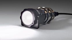
To date, very few commercially available systems are available that use this technique, the most notable being the Trevista system from Stemmer Imaging (Puchhein, Germany; www.stemmer-imaging.de). Already in use by Swoboda (Wiggensbach, Germany; www.swoboda.de) to analyze the surface of metal-plastic automotive components, the assemblies are first placed under a dome light that is used to illuminate each part with diffuse light from four different directions (Figure 2). Four synthetic images are then computed that represent the local slope of the surface in x and y directions and the topography and texture of the surface (see "Shape from shading images steering components," Vision Systems Design, June/July 2014, http://bit.ly/1s9BDxw).

While such systems could be termed active imaging systems (since the lighting used is not ambient), other active 3D systems provide their own source of illumination often in the form of laser light. This approach can be especially beneficial when smooth featureless objects must be imaged since it is easier to extract correspondences.
Structured lighting
Laser light used in such systems often employ structured laser light or two-dimensional laser grid projection. To generate a 3D image using structured light, a camera is used to record the projected coherent laser beam reflected from the object's surface. Since the geometry of the camera and laser combination is known, the coordinates of the projected laser beam can then be calculated by triangulation.
As the object or camera/laser system moves across the field of view of the object, X, Y, and Z coordinates are measured and used to generate a point cloud that represents the external surface of the object. This point cloud can then be projected onto a plane to produce a depth map providing a 2D image that replaces intensity values with depth data.
Like passive stereo-based systems, the laser and camera used in structured light systems can either be configured separately or purchased in a pre-calibrated system. To generate this structured laser light, companies such as Coherent (Santa Clara, CA, USA; www.coherent.com), Osela (Lachine, QC, Canada; www.osela.com), ProPhotonix (Salem, NH, USA; www.prophotonix.com) and Z-LASER (Freiburg, Germany; www.z-laser.com) all offer highly uniform lasers that are available in number of different wavelengths and line widths. Reflected laser light is then captured using a CCD or CMOS-based camera.
While any such camera can be used to capture the reflected laser light, it is often necessary to use a camera with a high dynamic range since the light may vary greatly in contrast. For this reason, high dynamic range cameras such as those from Photonfocus (Lachen, Switzerland; www.photonfocus.com) are often used in such applications.
While a single camera and structured laser light source can be deployed, if any point on the object is occluded with either respect to the light source or the camera, an incomplete line profile will be imaged. In such cases, multiple light sources and/or cameras can be used.
To support such functionality, software packages used for 3D reconstruction such as 3DExpress from Aqsense (Girona, Spain; www.aqsense.com) allows developers to configure 3D imaging systems using two laser lines and one camera. In such a configuration, the software calibrates the system, generates the point cloud from each laser line, and merges the image data in a single combined output.
Like stereo-based systems that use two cameras, structured light systems demand accurate calibration between the light source and the camera. And like stereo systems, this can either be accomplished by using separate structured light generators and cameras or by purchasing pre-calibrated systems from companies such as LMI Technologies (Delta, BC, Canada; www.lmi-technologies.com), Tordivel (Oslo, Norway; www.scorpionvision.com) and SICK (Waldkirch, Germany; www.sick.com).
Software provided with these products allows developers to capture scans and build these into 3D models that can be then be further processed using third-party machine vision software from companies such as Matrox (Dorval, QC, Canada; www.matrox.com) and MVTec (Munich, Germany; www.mvtec.com). Software packages such as the Scorpion Vision package from Tordivel, allow developers to develop more accurate part pose estimation by matching CAD models to these 3D images.
This is the approach taken by Tordivel in the development of a 3D bin picking system developed in conjunction with Dynatec (Askim, Norway; www.dynatec.no) for a dog food packaging manufacturer. In operation, the system uses a Scorpion 3D Stinger MLaser stereo camera/laser system to capture 3D images of sausages. After extracting 3D data from the scene using the company's Scorpion vision software, a 3D cylinder model is then used to match the captured 3D image and cylinder model.
Projected textures
Like structured light-based 3D systems, projected texture stereo vision systems can also be used in applications where images of objects with little texture must be found. In operation, known patterns are projected onto the object using laser or LED-based pattern projectors and the reflected light is captured using a stereo camera system.
Such products can take many forms including those that project patterns of crosses, circles, squares, dot-matrices, multiple lines and random dot matrices. The choice of which pattern generator to use will depend on which provides the best correspondence between features of the two stereo images.
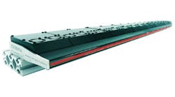
IDS Imaging Development Systems (Obersulm, Germany; http://en.ids-imaging.com), for example, uses a random point pattern projector in its pre-calibrated Ensenso stereo 3D camera system (Figure 3), a system that has recently been deployed by bsAutomatisierung (Rosenfeld, Germany; http://bsautomatisierung.de) in a system that automatically picks individual, randomly aligned parts from a container (see "3D vision system assists in robotic bin picking," Vision Systems Design, http://bit.ly/1qWBIUB).

Fringe projection
As a variation of the structured light technique, digital fringe projection systems use a projector to project a series of phase-shifted sinusoidal fringe patterns onto an object, a task often relegated to a digital light projector (DLP). Distorted reflected fringe image patterns at differing phase shifts from each other are then captured by a camera. A phase recovery and phase unwrapping algorithm can then be used to generate an absolute phase map that can be converted to a 3D point cloud to represent the surface structure of the object.
To date, a number of different companies offer products based around this technology, including the Mephisto scanner from 3D Dynamics (Gravenwezel, Belgium; www.3ddynamics.eu) that uses a DLP from InFocus (Portland, OR, USA; www.infocus.com) and a FireWire camera from Allied Vision (Stadtroda, Germany; www.alliedvisiontec.com) to generate 3D images at 30 frames/s. GFMesstechnik (Berlin, Germany; www.gfmesstechnik.com) and ShapeDrive (Munich, Germany; www.shape-drive.com) both offer 3D scanners that integrate both the projection light source and CMOS camera into single units.
While the GFMesstechnik design uses a TI DLP to perform digital fringe projection, engineers at ShapeDrive opted to use an LCOS light engine (see "Scanners use light projectors for fast 3D image reconstruction," Vision Systems Design, February 2011, http://bit.ly/1Fc7jsV).
Flight time
While stereo vision, structured light and fringe pattern projection systems can generate 3D depth data, a number of time of flight (TOF) techniques can also be used. These products incorporate illumination sources and solid-state imagers that illuminate objects within a scene with a modulated light source and then measure the phase shift between the illumination and the reflection to determine distance measurement.
To detect these phase shifts, the object is either illuminated by a pulsed mode or continuous wave (CW) illumination source. Different methods are then used to determine the phase shift (see "Time-of-flight camera - An introduction," Texas Instruments White Paper; http://bit.ly/1waS52i).
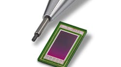
For its part, odos imaging (Edinburgh, Scotland; www.odos-imaging.com) has chosen a pulsed technique in the design of its real.iZ-1K-VS vision system. In operation, pulses light reflected by objects within the scene are detected by a 1280 x 1024 CMOS imager and range information computed. Simultaneously, an intensity image of the scene is captured allowing the system to capture both distance and intensity information (Figure 4).

While odos imaging has chosen to use a pulse technique Mesa Imaging (Zurich, Switzerland; www.mesa-imaging.ch/), ifm efector (Exton, PA; www.ifm.com) and PMD Technologies (Siegen, Germany; www.pmdtec.com) use continuous wave (CW) techniques (see "3D imaging systems target multiple applications," Vision Systems Design, http://bit.ly/1yKkujf).
Choosing which type of 3D vision system to use is highly dependent on the parts that need to be measured. While laser range finders using time of flight methods can be used to locate distant objects, stereo imaging systems may be better suited to imaging high-contrast objects. Where such objects are highly specular, it may be more useful to employ projected texture techniques. Luckily, numerous articles are now available to guide the systems developers towards the correct choice of 3D imaging systems (see "More 3D Imaging on the web").
More 3D Imaging on the Web
• State-of-The-Art and Applications of 3D Imaging Sensors in Industry, Cultural Heritage, Medicine, and Criminal Investigation (http://1.usa.gov/1rj11gG)
• A Review on Commercial Solid State 3D Cameras for Machine Vision Applications (http://bit.ly/1rj16B3).
• Robot Vision in Industrial Assembly and Quality Control Processes (http://bit.ly/1vFt7uc).
• Advantages of 3D Time-of-Flight Range Imaging Cameras in Machine Vision Applications (http://bit.ly/Zy5xkZ).
• 3D Image Sensors, an Overview (http://bit.ly/1rJ95aw)
• Obtaining shape from shading (http://bit.ly/1CxgeRF)
• Projected texture stereo (http://bit.ly/1wjgAeK)
• IKVA Newsletter - 3D Vision in Action (http://bit.ly/1icBoOM)
• High-resolution, real-time 3D imaging with fringe analysis (http://bit.ly/1wQsSt3)
• Time-of-Flight Camera - An Introduction (http://bit.ly/1waS52i)
• Structured-light 3D surface imaging: a tutorial (http://bit.ly/11FBqtn)
• Why 3D imaging is important in robotics applications - Vision Systems Design webcast (http://bit.ly/1rtoPOU)
Companies mentioned
3D Dynamics
Gravenwezel, Belgium
www.3ddynamics.eu
Allied Vision
Stadtroda, Germany
www.alliedvisiontec.com
Aqsense
Girona, Spain
www.aqsense.com
bsAutomatisierung
Rosenfeld, Germany
http://bsautomatisierung.de
Coherent
Santa Clara, CA, USA
www.coherent.com
Dynatec
Askim, Norway
www.dynatec.no
GFMesstechnik
Berlin, Germany
www.gfmesstechnik.com
IDS Imaging Development Systems
Obersulm, Germany
http://en.ids-imaging.com
ifm efector
Exton, PA, USA
www.ifm.com
InFocus
Portland, OR, USA
www.infocus.com
LMI Technologies
Delta, BC, Canada
www.lmi-technologies.com
Matrox
Dorval, QC, Canada
www.matrox.com
Mesa Imaging
Zurich, Switzerland
www.mesa-imaging.ch
Motoman
Miamisburg, OH, USA
www.motoman.com
MVTec
Munich, Germany
www.mvtec.com
odos imaging
Edinburgh, Scotland
www.odos-imaging.com
Osela
Lachine, QC, Canada
www.osela.com
Photonfocus
Lachen, Switzerland
www.photonfocus.com
PMD Technologies
Siegen, Germany
www.pmdtec.com
Point Grey
Richmond, BC, Canada
www.ptgrey.com
ProPhotonix
Salem, NH, USA
www.prophotonix.com
Robotic Vision Technology
Bloomfield Hills, MI, USA
http://roboticvisiontech.com
ShapeDrive
Munich, Germany
www.shape-drive.com
SICK
Waldkirch, Germany
www.sick.com
Stemmer Imaging
Puchheim, Germany
www.stemmer-imaging.de
Swoboda
Wiggensbach, Germany
www.swoboda.de
Tordivel
Oslo, Norway
www.scorpionvision.com
University of Tokushima
Tokushima, Japan
www.tokushima-u.ac.jp
Z-LASER
Freiburg, Germany
www.z-laser.com