HIGH-SPEED IMAGING - Smarter ICCD cameras exploit their speed potential
The latest generation of research-grade imaging and spectroscopy ICCD cameras uses novel software-customizable approaches to signal readout management and intensifier gating, delivering thousands of images or spectra per second in continuous operation and tens of thousands of acquisitions per second in burst mode
By Antoine Varagnat, Gerald Cairns, and Gary Hancock
Intensified CCD (ICCD) cameras are principally known for delivering high temporal (fast gating) resolution as well as single-photon detection capability, although the latter has been strongly challenged by electron-multiplying CCDs (EMCCDs) in recent times.1, 2 Traditional laboratory ICCDs, which have slow signal-acquisition cycles and limited portability, face growing challenges from the market to provide information more quickly and accurately in a wider range of demanding environments. These include online process and quality control, remote in-field health-hazard detection and monitoring, and analysis of extremely irradiation-sensitive, photobleachable biological samples. New “intelligent” acquisition modes now fully exploit ICCDs potential, delivering higher speeds and signal-to-noise ratios (SNRs).
An ICCD consists of an image intensifier mated to a cooled CCD array through fiberoptic plate interfaces to deliver the highest optical throughput. Incoming photons impact the photocathode (the input photosensitive layer), which can be “gated” to accurately temporally isolate useful signals at nanosecond speeds, therefore acting as an optical shutter. The resulting photoelectrons are accelerated and directed toward a thin honeycomb microchannel plate (MCP). The photoelectron cloud is amplified up to hundreds or thousands of times within the narrow channels in the MCP. A phosphor screen then converts the electron cloud back into visible photons that are directed through a fiberoptic plate assembly onto the CCD for detection. The subsequent signal is finally read either as an image or a spectrum.
Crop mode
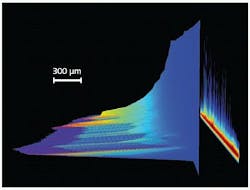
When considering the study of pulsed excitation-induced phenomena in fields as diversified as material ablation, radio-frequency plasma-kinetics analysis, particle or other object tracking by laser-induced fluorescence (LIF), or atomic/chemical microspectral mapping by laser-induced-breakdown spectroscopy (LIBS), high acquisition speed is usually a prerequisite (see Fig. 1). These speed requirements can be dictated by the need to maximize temporal sampling frequency of a fast transient behavior, or to perform multiple signal accumulations of the same phenomena in order to deliver a workable SNR in the shortest timeframe possible.

When it is possible to precisely focus the useful signal from the experiment onto a few rows at the bottom of the CCD matrix (that is, next to the serial readout register), a mode known as “crop mode” can be used to achieve continuous acquisition rates up to hundreds of subimages per second or a few thousands of spectra per second (sps). By defining—through a dedicated software interface—the number of rows actually illuminated on the lower part of the sensor, crop mode allows the user to only read this specific section after each exposure. The next acquisition starts while the last exposure contribution is clocked to the readout node at several megahertz through the masked readout register, providing the best sensor-readout management to achieve the fastest acquisition rates.
Careful selection and positioning of imaging optics, or fiberoptic coupling in the case of a spectrograph, are essential to precisely image the useful signal onto the few sensor rows targeted while minimizing the stray light falling on the upper part of the sensor’s active area.
How fast can this crop mode operate? This will always depend on the number of sensor rows being used. For imaging applications using the popular 1024 × 1024-pixel array with 13 × 13 μm high-resolution pixels, frame rates as high as 333 Hz can be achieved with a 1024-pixels-by-10-rows-high illuminated area.
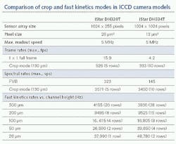
When it comes to spectroscopy sensors, acquisition rates can be considerably faster. This is because recording spectra can be reduced to a one-dimensional task—the critical information is essentially intensity versus CCD column, often without the need for spatial information regarding the location of the emitted signal in the sample. Therefore, all the pixels within one CCD column can be binned into the readout register before actual readout of the overall signal. In that scenario, this can mean accessing spectral rates in excess of 3500 sps.
Fast kinetic mode for fast-burst studies
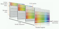
However, even data-acquisition rates of hundreds of images or thousands of spectra per second may not be fast enough for some applications. Fortunately, an alternative intelligent operating mode called “fast kinetics mode” can provide even faster speeds in rapid burst sequences. Experiments based on laser flash photolysis, pump-probe setups, rapid scanning of the probe laser delay, and fast transient absorption can all benefit from this superior acquisition speed. Whereas crop mode exploits the full potential of the CCD’s fast readout amplifier, fast kinetic mode exploits the even faster vertical clock speed (row to row shifting). This takes only a few microseconds in the most advanced ICCDs such as Andor’s new iStar. As with crop mode, just a few rows of the CCD array are used to record each image or spectrum. But in fast kinetics mode, these are the topmost rows of the array; the rest of the array is used as a high-speed storage register.
The image or spectrum is acquired in n rows where n is set by the operator through a dedicated software interface (see Fig. 2). The image is then rapidly shifted into the adjacent n rows. The process is repeated until the entire CCD array is filled up, terminating this burst sequence, which can be repeated again after the entire array has been fully read out via the serial readout register. The maximum speed of the fast kinetics mode is set by the number of rows used for each image/spectrum and the vertical clock speed of the CCD. For example, with clock speeds of a few microseconds, eight rows can be imaged at a rate of nearly 17 kHz. The length of the burst is also determined by the number of rows being used for each image/spectrum. For example, with eight rows and a 1024 × 1024-pixel array, this means (1024 - 8)/8, or 127, images can be sequentially acquired in a single burst, as the top eight illuminated rows cannot be used for storage.
A rate of 17,000 data acquisitions per second equates to a temporal resolution of around 60 μs, which may be insufficient for some fluorescence decay/lifetime studies. However, this temporal accuracy is improved by orders of magnitude by taking advantage of the fast gating capabilities of the ICCD photocathode.
Integrate on chip
While sensors dictate the rate at which individual images or spectra can be discriminated in time throughout a series of acquisitions, image intensifiers set the ultimate timing resolution for precisely isolating phenomena. This enables so-called “gating out” of the excitation sources such as lasers or flash lamps, and “gating out” unwanted excitation-induced background signal such as the continuum that appears after laser ablation in LIBS setups. It also enables extremely high timing sampling granularity to precisely reconstruct pulsed plasma or fluorescence-lifetime behavior profiles, for example. The photocathode opening time can be software-controlled over time periods from nanoseconds to milliseconds, while the gating delay from the excitation source can be adjusted with 10 ps accuracy for the latest generation of ICCDs.
Some experimental scenarios can lead to intrinsically low photon fluxes per excitation occurrence. This may be due to a number of reasons such as the temporal sampling requirement, unwanted signal-gating requirements, or the photobleaching susceptibility of biosamples. This in turn can pose challenges to achieving acceptable SNR. Increasing the intensifier gain can be useful up to a certain level, beyond which further gain provides no advantage and at extremes can lead to a lower SNR. This is due to an increasing influence of photocathode thermal noise and shot noise.
One can, however, take advantage of experiments using fast-repetition-rate lasers (from 10 Hz to hundreds of kilohertz) to maximize SNR in a shorter timeframe while maintaining the photocathode timing and gating accuracy. Specifically, when the excitation-source frequency exceeds the acquisition rate of the CCD (that is, when several useful signal occurrences happen during a single CCD exposure), integrate-on-chip can be used to precisely track and accumulate every useful signal contribution prior to each sensor readout (see Fig. 3). The latest generation of ICCDs can make use of every single signal contribution generated at rates up to 500 kHz without any alteration of the gating voltage level, thus maintaining the best system spatial resolution.
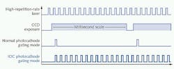
With normal mode operation, the photocathode is activated for as little as 2 ns of the total millisecond CCD exposure time. For the rest of the exposure time, the system is simply accumulating dark noise. But with integrate-on-chip, this time can be spent accumulating useful signal. Here the photocathode is still synchronized with the same delay relationship relative to the laser pulse, but it is allowed to open many times during each CCD exposure. For low signal levels, this is an optimum way to rapidly build up data with a good SNR.
REFERENCES
1. C.G. Coates and D.J. Denvir, “Optimizing low-light microscopy with back-illuminated electron multiplying charge-coupled device,” J. Biomed. Opt., 9, 6 (November/December 2004).
2. D.J. Denvir and E. Conroy, “Electron Multiplying CCD Technology: The new ICCD,” SPIE Proceedings Series, 164 (2002).
Antoine Varagnat and Gerald Cairns are from Andor Technology, Belfast, Northern Ireland. Gary Hancock is from Andor Technology USA (South Windsor, CT; www.andor.com).
*This article was first published in Laser Focus World, Vol. 47, No. 9, September 2011.