Improvements drive color linescan imaging
New sensors refine the linescan spatial-resolution/cost compromise by moving to multiline technology.
By Winn Hardin, Contributing Editor
Charge-coupled-device (CCD) and complementary-metal-oxide-semiconductor (CMOS) line-scan, or linear-array, cameras are designed for scanning applications where the minimum spatial resolution is extremely small in relation to the total image size. Examples include ultrahigh-resolution inspection of semiconductor wafers, large-area webs, timber, and food.
By stitching the image readout from a ‘line’ sensor formed by thousands of pixels in a single row versus an area sensor (for example, a 2k × 1 linear sensor vs. 2k × 2k-pixel arrays), linescan cameras can generate extremely high-resolution images, thousands of pixels wide, at a fraction of the cost of an area-array camera. However, higher resolution comes at a price, including exponentially higher illumination requirements and increased time-synchronization demands-both of which increase the cost of a machine-vision system.
Manufacturers have improved lighting budget limitations with color linescan cameras by using multiple line sensors and binning the results. This improves the sensitivity and cost of the sensor, but can complicate synchronization, optical alignment, and camera integration into the machine-vision system. However, new dual-line sensor architectures are emerging that could significantly simplify performance and integration issues, potentially reducing the cost and complexity of high-speed, high-performance linescan machine-vision applications.
Light vs. Linescan
Because linescan sensors are essentially one-dimensional sensors within the context of a machine-vision application, objects have to pass underneath the camera or the camera has to scan the object to create a 2-D image by acquiring and stacking line after line of image data. In production environments, the faster the camera scans, the faster the system’s throughput. While an area array acquires all pixel values at once and only requires a single illumination for this event, a linescan camera needs to acquire 2000 ‘lines’ to create the same image as a 2k × 2k area-array sensor. As the production lines (and, therefore, cameras) are pushed faster and faster, this budget issue becomes a major limiting factor based mainly on photon shot noise and dark current.
“You can increase the full-well capacity of a pixel, which is dynamic range, but the challenge is to fill that pixel with photons,” explains Joachim Linkemann, product manager at Basler Vision Technologies. “For lower line rates between 5 and about 30 kHz, I recommend a CCD sensor because the read noise is slower on a CCD, and image quality and behavior of CCDs over time are well understood. When the application calls for higher speeds or higher resolutions, I recommend CMOS technology, which is coming closer and closer to the image quality of CCDs. Ultimately, it comes down to signal-to-noise ratio and read noise to determine what kind of sensor one should use in a linescan application.” Two of the most common noise sources in high-speed applications are photon shot noise and dark current.
Photon shot noise is a statistical phenomenon following a Poisson distribution resulting from the random variation in the number of discrete photons striking the photosensor. Arising from the quantum nature of light, photon shot noise cannot be separated from the signal itself and cannot be electronically or algorithmically corrected as can fixed pattern noise. And because it scales sublinearly with the collected charge, it becomes a progressively more dominant noise source as the available light decreases (for example, halving the number of photons only reduces the shot noise by 1-1/√2 or ~30%). In low-light applications, photon shot noise will eventually limit the sensor and camera noise floors.
Dark current is noise generated by thermal activity in the light-sensitive area of a sensor, resulting in a signal even when light is not present. The sensor must be able to produce based on collected photons that exceed these combined noise sources if it is to produce a valuable image. Luckily, the higher the speed of the application, the shorter the time between sensor exposures and, therefore, the less dark current.
Two Better Than Three?
Until the recent advent of color dual-line and new trilinear color linescan architectures, color linescan CCD and CMOS cameras came in three basic architectures: 3CCD prismatic, trilinear, and single line (see “Linescan architectures,” p. 42). A new group of color linescan cameras from DALSA use dual linescan CCD architecture for the Spyder3 series and trilinear CCD technology to back the Piranha color CCD cameras. Basler offers CMOS-based linescan cameras in its Sprint series. In each case, the trend is toward refining the linescan spatial-resolution/cost compromise by moving to multiline technology that offers high resolution and easier optical integration.
All three cameras place linear arrays on the same die, in very close proximity, reducing optical alignment issues common to filtered, less-expensive linescan cameras. Both manufacturers achieved this by moving the read out electronics while taking different approaches to improving light sensitivity.
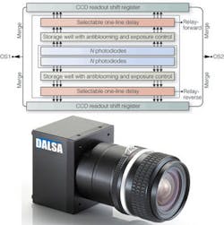
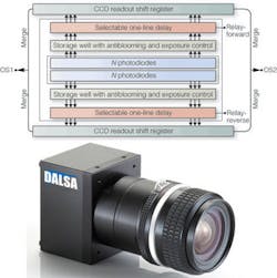
The dual linescan Spyder3 CCD camera is designed functionally similar to time delay and integration (TDI) arrays and therefore uses binning to improve light sensitivity, which is easier to implement in a CCD than a CMOS imager. Unlike traditional TDI cameras, however, the fact that the sensor has only two lines allows the polysilicon gate, traditionally on top of the light-sensitive area, to be moved to the side of the pixels, improving blue and UV response (see Fig. 1).
The dual linescan architecture behind the camera consists of two parallel arrays of photodiode pixels with each pixel connected to a selectable, bidirectional delay gate that either allows charges through or delays the charges by one scan line in either direction. Because of the proximity of the rows and the connecting gate, the consecutive image acquisition by each row is triggered through an internal time delay and does not require an external encoder to reduce blurring. Electrons from the two arrays (one of which has been delayed) are then combined on-chip into a single output with no increase in amplifier noise, a doubling of sensitivity and only a √2 increase in photon shot noise. Also, because of the short integration time common to many linescan applications, dark current noise is minimized.
The trilinear Piranha color linescan CCD camera uses a unique architecture that allows the 10-µm pixel rows to be placed within 20-µm of the neighboring row, which represents a 3X reduction in line spacing. According to DALSA’s Dave Cochrane, director of product management, this translates as a 3X improvement in depth of field, which helps to ease the optical alignment issues common to nonprismatic trilinear cameras. Although the Spyder3 is available in a custom color version, DALSA is promoting the Piranha color camera as the heir to their lineup of Piranha linescan cameras that offer high speed, image quality, and large depth of field for high-speed imaging applications.
“With ownership and control of our own foundry, we are able to customize sensors to improve performance in monochrome and color linescan applications,” Cochrane says. “DALSA’s experience with CMOS linescan shows it can be adapted to unique custom applications in the market; however, for general-purpose machine vision, CCD linescan has a long life ahead of itself. We see that further CMOS linescan developments need to occur before they begin to offer similar performance in dynamic range or image quality.”
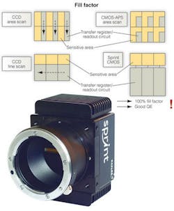
Basler’s Sprint camera uses a CMOS sensor in a dual line configuration. Again, by moving to only two lines, readout amplifiers are moved to either side, enabling 100% front fill factor on pair with CCD linescan cameras. Moving to 100% fill and improving the readout electronics has allowed the Sprint sensor to achieve line rates up to 140 kHz. Also, because the two rows are in closer proximity than CCD architectures, optical alignment is improved and distortion minimized (see Fig. 2).
The Sprint architecture also uses a Bayer filter to achieve color imaging, alternating the top line of pixels with red and green filters and the bottom line with blue and green filters, producing the high green response that mimics the response of the human eye. However, because it lacks a programmable delay gate, the Sprint design is unidirectional. All linescan cameras require tight control of the conveyor, limiting side-to-side jitter that can cause image blurring.
In the past, the dynamic range and image quality of CCD sensors have promoted this architecture over CMOS when it comes to linescan cameras, particularly those used in demanding high-resolution, high-speed applications. However, continuous improvement in CMOS manufacturing process, leading to more uniform pixel response, large-scale integration, and the potential for lower noise floors, are pushing sensor makers to pursue CMOS for both monochrome and color linescan applications.
“A big potential for CMOS is that you can implement A/D conversion at the pixel level, significantly decreasing heat dissipation even at higher clock speeds. So you’re able to design sensors that run fat faster than CCDs without exploding the price of the package and mechanics,” explains e2v’s Christophe Robinet.
null
Linescan architectures
Prismatic linescan cameras have a prism between the lens and the focal plane. The prism splits the incoming light and is read out by three separate linescan sensors: one each for red, green, and blue. By combining the pixel values from N1, N2, and N3, where N describes the pixel position in the row and 1, 2, 3 indicate individual linear sensors, the camera’s readout electronics create a single RGB combined value for each pixel in the resulting image.
“With trilinear [prism] cameras you split the light and measure it all at one time,” explains Christophe Robinet, camera marketing manager at e2v. “You have no delay, excellent modulation transfer function, and excellent color separation. In the end, that translates to good sensitivity because you lose less light than with color filters, which is critical to high-speed linescan applications. There’s also no loss of light because the prism is designed to overlap the spectrum for each sensor. The drawback is cost and size because the optics are expensive to get the best color correction.”
e2v will soon introduce a quad-linear CCD linescan camera that will include a fourth sensor for either unfiltered monochrome or near-infrared. The addition of infrared will improve color differentiation, Robinet says, which is important for printing and other Web applications where colorimetry, rather than spatial resolution of features, is the driving criterion.
At the other end of the linescan camera price list is the single-line color camera. This approach uses a single linear array overlaid with bandpass filters to create a single color image pixel. A repetitive series of color filters (red, green, blue, repeat) are applied to consecutive pixels on the sensor to create triplets of sensor pixels that will result in a single color image pixel value. Like prismatic multilinescan camera, these cameras can scan in either direction because they do not need to internally combine multiple sensors, each with its own physical location in respect to the object under test. The downside to this approach is that spatial resolution is reduced to one-third of the sensor’s total number of pixels because three sensor pixels are required to generate one color-image pixel.
A third option offers a compromise between spatial resolution and price at the cost of optical alignment, sensitivity, and integration complexity. By applying color filters to three separate linear arrays (one red, one green, one blue), spatial resolution is maintained while reducing the cost of the camera by eliminating the need for the more optically efficient prism and associated optical elements. However, this approach essentially creates three separate focal planes inside the camera (one for each linescan sensor), requiring specific camera placement in relation to the object under test.
“Filters on CCDs don’t produce quite the color separation that prismatic cameras do,” notes e2v’s Robinet, “and you also have to correct for the distance between lines. Synchronization is difficult, but more important, the optical challenges mean you can only place the [filtered multilinescan] camera perpendicular to the scene. It’s not as much a problem with flat 2-D surfaces, like webs, but as soon as it becomes 3-D, like rice grains on a conveyor, you quickly come up against optical limitations.
“Most sensors made by Kodak, Toshiba, or Sony, which were mainly developed for flat-scene and scanning applications, aren’t overly concerned about the distance between the lines of the sensor. If the grain of rice moves between the acquisition of the red and green line of the camera, then you have a blurred image. The trick is to reduce the distance between the lines to ease these restrictions. What is changing is we have a new generation coming that has short distances between lines, simplifying the life of the user. It’s easier to tilt the camera and observe 3-D goods because the camera runs quick enough that the distance shift is negligible.” -W.H.


