Process Precision

C.G. Masi, Contributing Editor
Applying mold release agent to unfinished, uncured tires just before molding them into their final shapes and vulcanizing them for strength and durability is typically a blind process. Manufacturers know the parameters—where tires sit in their spray machines, their shapes and how gravity deforms them as they hang in the spray area, and how much spray is needed—in a statistical way. Their automated equipment, however, cannot sense the variations from tire to tire.
When Cooper Tires wanted to upgrade its manufacturing operation in Albany, GA, it asked Pioneer Industrial Systems to create a system that was smarter than the average automated tire sprayer. Pioneer’s team decided noncontact measurement of every green carcass using machine vision was the best approach.
“We decided to use machine vision,” says Todd Hendricks, president of Pioneer, “because it gives the exact profile of the tire. It turns this system into an intelligent robotic system because it’s reacting to what the camera is seeing.”
Variations of green
Automobile tires come in many shapes and sizes. Uncured or “green” tires exhibit variations in size and shape even within a particular tire model.
“The tires are all mixed in coming down the line,” Hendricks points out, “so each tire is a different size, shape, and profile. Also, you could have two tires that are the same barcode or SKU number, but the tires settle differently on the conveyor, so when you go to spray them, even though they are the same tire they may have a different profile just because of the way the rubber is deformed on the conveyor.”
Automobile tires are composite assemblies of many different compounds for the cord, sidewalls, and tread all bonded together and cured by vulcanization. Each tire carcass starts out as mats of the different materials laid up to form the general tire shape.
The exact dimensions and tread pattern are impressed on each tire in the final molding step, where a pneumatic bladder inflates to press the green tire against the inside of a mold to form the outside shape of the tire. At the same time, the mold press heats the tire to crosslink the synthetic rubber molecules, making them harder and stronger. This step permanently bonds the layers together to prevent separation under highway use.
After vulcanization, the cured tire would stick to the pneumatic bladder on the inside and the heated mold on the outside unless protected by a thin layer of mold-release agent. Too thin a layer causes the tire material to stick in the mold. Too thick a layer wastes release agent and can cause problems of release agent getting into places it does not belong.
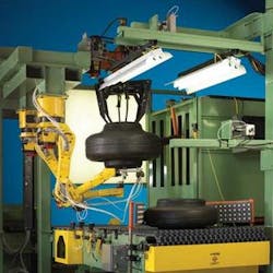
To completely coat the carcass with the mold release spray in one operation, tire manufacturers hang green tires from calipers, which are multipronged hooks that support them at a few points on the inner edge that will become the tire bead (see Fig. 1). The tire is held by only one of the inner beads, and so gravity stretches the upper sidewall more than the lower sidewall. Since the ideal spray pattern leaves a layer of mold-release agent that will be uniform over the entire tire when it is in the mold, the sprayer needs to adjust for this stretching. (See video, “Intelligent robotic system applies tire mold-release spray,” at www.vision-systems.com.)
null
Presentable carcass
Pioneer designed a machine that automatically presents each green carcass to the caliper, then measures the exact profile with a machine-vision system. It then calculates exact parameters for the sprayer. Two Fanuc Robotics M-6iB SCARA robots each carry a spray gun: one to spray the outside and the other to spray the inside. Later versions of the workstation use a Fanuc M-10i robot.
To start, a conveyor moves the green tire onto a staging area next to a lift table. Two gates center the tire left to right as it moves onto the table.
A JAI TM-200 video camera with 16-mm lens is mounted over the staging area, looking down at the tire. Images are sent to a PC running Fanuc’s V-500i 2-D vision software, which performs two tasks. First, it measures the tire diameter and finds its center so that it can be positioned correctly to hang uniformly from the caliper. Second, it locates a barcode that must be masked to protect it from the release agent.
The tire then moves onto the lift table, which carries it up to the caliper jaws. The caliper rotates to bring the barcode mask—which is attached to one of the jaws—into position over the barcode, and the jaws open to catch the upper bead edge. The table then lowers, leaving the tire carcass suspended from the caliper jaws, with the mask covering the barcode.
At this point, a second TM-200 camera looks horizontally at the tire profile as it hangs from the caliper jaws. The tire is backlit against a white screen to provide a silhouette that can be digitized, thresholded, and the edge found (see Fig. 2, top).
The system looks for places where the profile changes direction rapidly to find the limits of the sidewalls and tread area. There are four important points: the upper bead edge, the point where the upper sidewall turns to form the tread area, the place where the tread area turns to form the lower sidewall, and the lower bead edge.
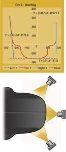
The analysis system draws line segments between these four points in pairs to approximate the upper sidewall, the tread surface, and the lower sidewall. These lines provide the basis for calculating the spray-gun positions and spray parameters for each of these surfaces.
The system then adjusts the spray-gun location and orientation, as well as the spray width, spray volume, and air pressure to provide an even coating over the entire outside of the tire carcass (see Fig. 2, bottom). Since the carcass is, at this point, of uniform thickness, the same profile lines can be used to make similar calculations for the inside spray procedure.
System architecture
The two cameras are part of the Fanuc Robotics Vision V-500i standalone grayscale 2-D vision system, a PC-based system used for finding part location and orientation (see Fig. 3). It also provides 2-D robot guidance for robotic material handling. Pioneer is now working on incorporating Fanuc’s IRVision into its systems.

The control system divides into three components, which communicate among themselves via Ethernet. The two robots—one to spray the inside and the other to spray the outside—operate separately using guidance information supplied by the vision system. The rest of the equipment, including the conveyors, is run by a separate Fanuc RX3i PLC that also communicates with the vision system via Ethernet. Thus, it is a distributed control system coordinated centrally by the vision system.
Hendricks reports that the machine, which cost $375,000, can spray about 250 tires per hour. “The machine has been really successful for them,” he says. “We did a customer follow-up and they’re getting very good coverage, uniform coverage, and significant amount of material savings, because we’re not wasting material. We’re minimizing overspray and putting the spray precisely where it needs to be.
“They were going to order four more, but because of the economy they put a hold on capital expenditures,” he adds. “However, we now have systems with tire manufacturers Cooper Tire, Bridgestone, Titan, and Carlisle Tire.”
Company Info
Cooper Tire, Findlay, OH, USA
www.coopertire.com
Fanuc Robotics North America
Rochester Hills, MI, USA
www.fanucrobotics.com
JAI, Copenhagen, Denmark
www.jai.com
Pioneer Industrial Systems
Pioneer, OH, USA
www.pioneerindsys.com