CAMERA SYSTEMS: Phase detection speeds camera autofocusing
Manufacturers of digital consumer cameras such as Canon and Nikon incorporate autofocusing mechanisms into their products to eliminate manual focusing. This technology is often disparaged by professional photographers; however, autofocusing has allowed many an amateur to capture sharp, high-resolution images without any knowledge of lenses, apertures, depth of field, or photographic composition techniques.
Certainly autofocusing has proved beneficial to consumers. It is also often used in machine-vision and image-processing systems where the focus point is indeterminate. Two different methods are commonly cited to perform autofocusing: contrast-detection autofocus and phase-detection autofocus.
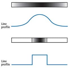
The first—contrast-detection autofocus—is accomplished by measuring the contrast of the image after it is captured. In this method, the intensity of adjacent pixels is compared. In an image that is blurred, the adjacent pixels will form a Gaussian curve, since pixel differences will vary slowly across the image (see Fig. 1). In a theoretically "perfectly sharp" image where, for example, the transition is from black to white across single adjacent pixels, this function will tend toward a unit impulse function.

The camera lens must be moved to achieve the sharpest possible transition. Because the optical system has no predetermined way of knowing this, the process is iterative and requires calculating the contrast difference every time the lens is moved.
To achieve optimal focus, the lens must then obviously overshoot the best in-focus point before iteratively settling on the correct focus for the image. One of the benefits of this approach is that the image sensor (more often, a field-programmable gate array, FPGA) in the camera can be used to perform the autofocus function.
However, the iterative contrast-detection autofocus process is slower than alternative approaches such as phase-detection autofocus. Phase-detection autofocus can result in a much faster focusing time.
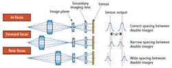
Phase-detection autofocus is radically different than contrast detection. Instead of using a single image sensor to perform autofocusing, phase-detection systems employ two separate detectors (see Fig. 2). While images of the object are captured on a primary image sensor, a separator lens in the optical path allows two additional images of the object to be captured by a secondary image sensor.
To perform autofocusing, the distance between these two images must be calculated. If the focal plane is in front of the camera lens relative to the primary image sensor, the distance between the two images will be narrower than the optimum value and vice versa. By computing the distance between these images, the lens is then moved in a specific direction until the image is in focus. Unlike contrast detection, this operation is not iterative so it is much faster—albeit more expensive in terms of hardware.
In computing the images' position on the secondary image sensor, both images must be analyzed for similar light-intensity patterns and the separation error calculated. Again, in this instance the image-processing function can be performed rapidly by comparing image intensities using an FPGA.