Flat-Panel Color Filter Inspection
Xing-Fei He and Frank Fang
Over the past few years, the demand for flat-panel high-definition televisions has resulted in the rapid growth of flat-panel display (FPD) production. To meet these demands,automated optical inspection systems (AOIs) have played a key role in increasing the performance and reducing the price of amorphous-silicon thin-film transistor liquid-crystal displays (TFT-LCDs). High-throughput AOIs based on linescan technology are required to meet the FPD industry’s zero-defect policies where not a single high-resolution panel can be shipped with a visible defect.
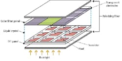
TFT-LCDs consist of a glass color filter panel and a TFT panel that are combined with a polarizer and backlight (see Fig. 1). These glass panels are filled with liquid crystal, which acts as a dynamic polarizing agent so that when a voltage is applied across the cell, the liquid crystal changes its orientation. Thus, various light intensities passing through each pixel of the panel can be controlled. To produce a color display, the color filter allows red (R), green (G), and blue (B) colors to be produced from the white backlight unit. To improve the contrast ratio between these pixels, a black matrix is coated around this color filter.
Many high-definition televisions are produced with 1920 × 1080 pixels; each pixel has three RGB primary colors, resulting in more than 6 million sub-pixels. By using 8 bits to represent each of the R, G, and B primaries, a true color 24-bit representation can provide a total of more than 16 million colors.
Flat-panel fabrication
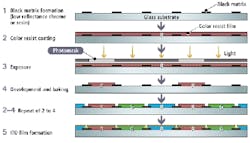
Manufacturing TFT-LCDs requires more than 200 manufacturing steps using a production line process that consists of TFT array/color filter fabrication, cell fabrication, and module assembly. In the fabrication of the color filter panel, a black matrix of chrome or resin is first deposited to prevent leakage of backlight and color crosstalk from adjacent pixels. Color filters consisting of either dye or pigment are then coated and patterned, respectively, for each RGB pixel (see Fig. 2).
During the process, cleaning, resist coating, exposure, development, and baking are repeated for each color. At each stage, AOI is used to inspect each of the primary color coatings and patterning. Finally, a transparent conductive indium tin oxide (ITO) film is coated on the panel and used as a common electrode. AOI is then used to inspect this ITO coating, after which the completed color filter glass, together with the TFT glass, is passed to cell fabrication.
To ensure that inspections do not slow the production process, the AOI system must operate in-line with the panel line. This helps minimize handling of the large, thin glass panel and thus avoids breakage. To avoid becoming a bottleneck in the production flow, the AOI system must also examine large sheets quickly with high enough resolution to detect and identify defects as small as 80 μm within individual sub-pixels. After detection, the location of these defects is used to direct repair efforts.
Most AOI systems are based on linescan camera technology. Unlike megapixel area-array imagers where a camera must transfer an entire megapixel image from the camera to computer before another image can be captured, only a single line from a linescan camera needs to be transferred to the host CPU before another line can be captured. This also allows linescan cameras to produce continuous images as wide as the camera’s field of view and of virtually unlimited length.
Finding defects
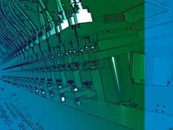
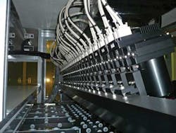
Integrating its expertise in optics, automation engineering, and image-processing algorithms, Utechzone has recently introduced a system for FPD manufacturers that incorporates visual inspection and automated handling. Known as Cobra AOI, the system can transport glass panels as large as 2500 × 2200 mm through a machine vision inspection station using either rollers or an air table (see Fig. 3, top).
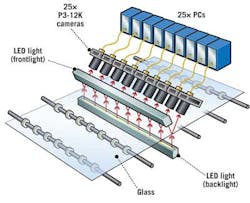
To illuminate the glass panel continuously as it moves through the system, custom front- and backside white linear LED lighting manufactured by Utechzone is used to simultaneously highlight both surface and internal defects.
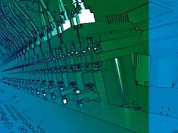
A bank of twenty-five Piranha3 12-kpixel/5-µm linescan cameras from Teledyne DALSA are each used to transfer 320 Mpixels/s over a Camera Link interface to twenty-five Teledyne DALSA Xcelera-CL-PX4 frame grabbers in twenty-five separate PCs (see Fig. 3, bottom). Operating at a working distance of 300 mm, each of the cameras is fitted with a 120-mm focal-length lens from Schneider Optics to provide a field of view of approximately 92 mm for each camera. This allows each camera to achieve a minimum object resolution of 7.5 μm.
Since each of the cameras captures a 12,288 × 1-pixel line of 8-bit pixels at 20,000 lines/s, more than 6 Gbytes of data are captured each second. In each camera, flat-field correction (FFC) is performed before data are transferred to Intel quad-core PCs, where a proprietary neighbor-comparison processing algorithm developed by Utechzone—using Teledyne DALSA’s SaperaLT software—is used to identify 7.5-μm defects. This allows the system to scan an entire panel in 18 s with a single scan and results in a total average cycle time (TACT) of 27 s with the panel moving continuously.
At the color-filter production stage, AOI is used to examine the color filter panel for a variety of defects, including particles on or pinholes in the dye or pigment, breaks in the black matrix, and remains in the glass. When the AOI system locates and identifies repairable defects, the panel is re-routed for possible repair. In the case of a nonrepairable defect such as a crack, manufacturers can adjust glass-cutting patterns downstream in the automation process to avoid incorporating such defects into finished panels.
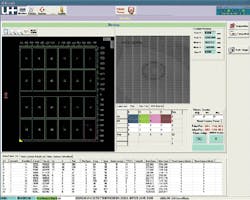
An operator employs a GUI to configure and manage the system (see Fig. 4). This interface displays a glass map of 6 × 4 displays to be cut into 24 displays, identified defects (top right), and a list of identified defects, includingx-y coordinates, width, height, size, and defect type. Defects identified are recorded along with their type and x-y coordinates. Glass that contains defects is later reviewed and then repaired in review-and-repair stations.
Future trends
While traditional color displays use red, green, and blue primary sub-pixels as a color palette, Sharp has recently introduced a four-color palette that uses red, green, blue, and yellow sub-pixels in its Quattron television line. For 8-bit/pixel sub-pixels, this increases the display palette from 16 million to more than 4 billion colors while improving the light transmission of the panel by approximately 20%. Adding a fourth color decreases the size of the sub-pixels, placing additional resolution demands on future AOI systems.
Color-filter-on-array (COA) technology is also allowing color filters and TFTs to be fabricated on the same glass panel. COA designs further improve optical transmission while reducing component costs. These complicated device structures impose further technical demands on AOI systems. Significant growth of low-temperature polysilicon (LTPS) technology used by LCDs in products such as Apple’s iPhone and iPad, and OLEDs used in products such as the Samsung Galaxy, also use very small pixels.
With these developments, further resolution demands on AOI systems are inevitable. Fortunately, camera technology is evolving to meet the challenges. At the ITE Show in Japan in December 2010, for example, Teledyne DALSA introduced a Piranha3 16-kpixel/3.5-μm linescan camera with a maximum line rate of 70 kHz, capable of delivering 1140 Mpixels/s over an HSLINK interface. Using such cameras in the next generation of color-filter inspection systems will result in systems of higher throughput while reducing the number of cameras and cables in a system.
Xing-FeiHe is senior product manager at Teledyne DALSA (Waterloo, ON, Canada) and Frank Fang is director of R&D at Utechzone (Tainan City, Taiwan).
Company Info
Schneider Optics
Hauppauge, NY, USA
Teledyne DALSA
Waterloo, ON, Canada
Vision Systems Articles Archives
