Lens Designs Tackle Novel Vision Applications
Telecentric, tilt, and polyview lenses are just some of the sophisticated optical designs supporting complex vision-based inspection applications
Andrew Wilson, Editor
Faced with inspecting an array of parts from a number of different manufacturers, machine-vision system integrators must carefully specify the optimum lens or lens combination that meets the needs of their application. Although relatively unsophisticated imaging systems can take advantage of several standard lenses, more complex problems require sophisticated optics. Luckily, a number of different vendors now offer these novel lens designs to allow otherwise difficult applications to be solved. These lenses are offered in different configurations depending on the applications they are required to support.
In machine-vision systems that perform precise part measurement, telecentric lenses have become increasingly popular. Though often more expensive than standard lenses, telecentric lenses allow precise, consistent, repeatable measurements. By eliminating the parallax error associated with standard lenses, objects closer to the lens do not appear larger than those further away over a defined telecentric depth (see “Telecentric lenses focus on machine vision,” Vision Systems Design, January 2004).
Telecentric designs
Telecentric lenses are offered as object space (object side), image space (sensor side), or bi-telecentric designs. Image space telecentric lenses are usually used in applications such as semiconductor projection equipment. These lenses are commonly found in lithography systems, for example, where the lithography mask must be imaged onto a silicon wafer. Object space and bi-telecentric lenses, on the other hand, are found in precision machine- vision metrology applications.
In object space telecentric designs, the chief rays of the lens are parallel to the object being measured, and the lens focuses the image onto the camera’s image sensor. Because the front element of an object space telecentric lens must be as large as the field of view of the object being measured, each individual application will dictate the size of the lens. Lenses are therefore often large and heavy and can be very expensive if the object or objects being imaged are very large.
Object space telecentric lenses are offered by a number of different vendors including Edmund Optics, Navitar, Light Works, Opto Engineering, Schneider Optics, and Sill Optics.
For educational purposes, Greg Hollows, director of machine-vision solutions at Edmund Optics, has prepared an educational video that compares standard lenses to telecentric lenses in three distinct imaging examples, illustrating the importance of using the correct imaging optics and optical principles to obtain the best measurements (see http://bit.ly/lqAHAY).
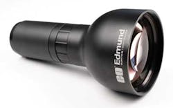
Many of these object space telecentric lenses are specifically tailored to operate with the large-format image sensors now being used in industrial cameras. Edmund Optics’ large-format 4-Mpixel telecentric lenses support up to 28.7-mm-diagonal sensors and offer greater than 40% contrast at 72 lp/mm across the sensor (see Fig. 1).
In high-precision machine-vision applications, it may be necessary to utilize a double-sided or bi-telecentric lenses. In such designs, telecentricity exists in both the object and image planes of the lens, further reducing optical and geometric distortion while providing uniform illumination across the image sensor. Objects within the depth of field of a bi-telecentric lens can move within a larger range than an object side telecentric lens while still retaining the same magnification. Many manufacturers offer these types of lenses. For use with 2/3-in. image sensors, Schneider Optics offers its range of Xenoplan bilateral (double-sided) telecentric lenses.
To increase measurement accuracy even further, a number of lens manufacturers provide collimated light sources for use with telecentric lenses. Unlike standard diffuse LED illuminators, collimated lighting allows object edges to appear sharper and thus provides higher measurement accuracy. IB/E Optics offers a modular telecentric illumination system consisting of a lens, illumination head, and power supply that can be used with a number of different lighting sources to supply telecentric illumination to objects under inspection.
Tilting images
Telecentric lenses are most often used in systems where the object to be measured is perpendicular to the system’s optical axis, but in some machine-vision applications an object may be positioned at an angle to the system’s optical axis, for example, if a part on a conveyor belt must viewed from a 45° angle. Shift/tilt lenses can be used to support these applications. The Scheimpflug principle allows the lens to be mounted at an angle to the plane of the sensor. By doing so, the in-focus plane can be changed from being perpendicular to the camera’s sensor to being at an angle to it.
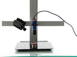
Many of these lenses are offered as products from companies such as Canon and Nikon for consumer digital SLR cameras (see “Shift/tilt lenses bring new perspectives,” Vision Systems Design, May 2006); tilt lenses such as the MCSm1-01X from Opto Engineering are employed to improve the accuracy of industrial 3-D machine-vision applications where a camera may be placed at an angle to the object being imaged (see Fig. 2).
Imaging odd objects
In addition to measuring flat surfaces, it is often necessary to measure curved surfaces such as the outside of bottles or containers. Many systems employ multiple cameras fitted with standard lenses to image multiple views of the object under inspection. To reduce the number of cameras and lenses incorporated in these applications, an alternative approach is to integrate a single camera fitted with a pericentric (or hypercentric) lens. This allows a single camera to be placed above the product to be inspected.
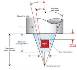
Since these lenses provide a converging view of an object, the top and sides of the object can be imaged simultaneously (see Fig. 3). In the Hyper-Eye pericentric lens series from Light Works, the lens receives rays of light as if they all originate from a single convergence point (CP). The distance from the front of the lens to the CP is called the convergence point distance (CPD); the object (in this case, represented by a square) is imaged within a maximum working distance of the CPD.
As can be seen, any object that is within the near viewing cone (NVC) can be focused onto the camera detector so rays of light that are collected at smaller angles will be imaged closer to the center of the detector and those at larger angles further from the center. Captured images must then be unwrapped using software to obtain a linear view of the sides of the object and perform image analysis (see “Smart optics and lenses image multiple views,” Vision Systems Design, December 2009).
One variation of the pericentric approach is the so-called catadioptric pericentric lens, which uses a Cassegrain design to reduce the length of the optical assembly. Such lenses provide 360° side-view images of small objects. With the PCCD Series from Opto Engineering, the sides of an object are imaged through the catadioptric system, while the top surface is directly imaged onto the center of the detector.
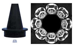
Some applications, such as the inspection of grommets or the threads of a nut, require that both the inner and outer walls of an object be imaged simultaneously. Telecentric lenses fitted with polyview optics (often referred to as polyview lenses) can be used to meet this requirement. With lenses such as the OE Polyview series from Opto Engineering, the object to be inspected is imaged from multiple 45° angles using a single lens (see Fig. 4). The eight 45° viewing angles allow the lens to image both the top and sides of a cylindrical object. Alternatively, if the object is a hollow cylinder (hole or cavity), the inner wall of the cavity can be imaged instead of the top, enabling both outer and inner wall inspection.
In many machine-vision applications, the use of telecentric lenses is now commonplace. Unlike conventional lenses that may exhibit viewing angle and magnification errors, the lack of perspective distortion with telecentric lenses allows machine-vision algorithms to more accurately determine the parameters of the objects being measured. More sophisticated pericentric and polyview lens designs—though useful in reducing the number of cameras and lenses required for any given application—require system integrators to develop software interpolation algorithms to render the images useful for further analysis.
Company Info
Edmund Optics, Barrington, NJ, USA
IB/E Optics, Hutthurm, Germany
Light Works, Toledo, OH, USA
Opto Engineering, Mantova, Italy
Schneider Optics, Hauppauge, NY, USA
Sill Optics, Wendelstein, Germany
