CAD software speeds lens selection, system design
Andy Wilson, Editor-in-Chief
Choosing cameras and lenses for a specific machine-vision task can be a daunting task, as developers must often sift through various data sheets from numerous camera and lens manufacturers. Even after specifying a lens/camera combination, performance of any particular combination is generally evaluated manually.
Understanding this, the European Machine Vision Association (EMVA) developed its 1288 standard as a unified method to measure specifications of cameras and image sensors used for machine-vision applications so that system developers might easily compare camera specifications or calculate system performance (see "EMVA-1288 Standard: Camera test systems go on show at VISION," Vision Systems Design, January 2011). With the introduction of the standard, companies including Sarnoff, Aphesa, Aeon Verlag and Studio, and Image Engineering developed systems to measure the specific performance of camera systems.
Using 1288 data such as quantum efficiency, noise, and spectral characteristics, softwareCAD tools such as the Vision System Designer (VSD) software from SensorDesk provide an interactive 3-D environment to model and analyze vision systems in an application-specific way.
"Because vision systems are often used in dimensional measurement and inspection," says Matthias Voigt, president of SensorDesk, "it is important to carefully select an appropriate lens for the task."
Several camera and lens combinations can be analyzed automatically to highlight the performance of each system utilizing the VSD software.
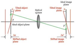
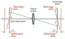
Leveraging lens specifications from manufacturers' data and the EMVA-1288 standard for cameras, the software can estimate the total dimensional measurement error for a camera/lens configuration by calculating error contributions from different factors—for example, when the target object or the image plane is shifted in the axial direction or when the object or image plane is tilted (see Fig. 1).
By automatically computing the error contributions from object-plane shift, object-plane tilt, image-plane shift, and image-plane tilt, as well as other factors such as lens distortion, the total error and thus the performance of different lens types can be analyzed for a specific working distance and field of view.
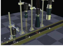
To demonstrate this capability, four camera/lens systems—which featured cameras with the same resolution and detector size—imaging the same field of view (FOV) were modeled (see Fig. 2). While system A has a 23-mm fixed focal-length lens, system B has a 70-mm telephoto lens, system C a 0.27X object-side telecentric lens, and system D a 0.3X bilateral telecentric lens.
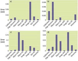
Figure 3a shows the measurement error terms for system A with a 23-mm lens. The total measurement error is 0.37 mm or 1% of the FOV. Here, axial object shift and object tilt are the dominant factors contributing to measurement error. Performing the same analysis on system C with an object-side telecentric lens, the errors for object shift and object tilt are reduced and measurement errors from part placement shift and tilt are now negligible due to the object-side telecentricity of the lens (see Fig. 3b). The total measurement error is reduced to 0.1 mm (or 0.3% of the FOV) and is now almost entirely caused by image and optical axis tilt.
Figure 3c shows the measurement errors for system D with a bilateral telecentric lens. Total measurement error is now reduced to 0.02 mm (0.06% of the FOV). Error contributions from image shift, image tilt, and optical axis tilt are negligible, and errors from the edge-detection algorithm are now dominant.
Comparing the 23-mm compact lens to the much longer 70-mm focal-length lens of system B, it can be seen that the total measurement error is 0.14 mm (0.4% of FOV), which is less than half the error compared to a 23-mm lens (see Fig 3d). With the longer focal length, axial object shift remains a dominant error term. This is in contrast to the object-side telecentric lens where the object-side shift and tilt errors almost disappear.


