Standard Gives Machine Vision Systems a New Image: Part II


Based on feedback from the vendor and user communities, the US-basedAutomated Imaging Association (AIA; Ann Arbor, MI, USA) recently announced that the GigE Vision technical committee had completed the development of Version 2.0 of the GigE Vision specification. This revision to the standard will further enhance the performance and reliability of GigE Vision systems.
Prior to the development of the specification, five key objectives were identified:
- 1) Increase throughput
- 2) Carry more data
- 3) Minimize transmission overhead
- 4) Improve determinism
- 5) Optimize flow control
To increase throughput, the GigE Vision technical committee formally introduced the 10 Gbit/s Ethernet (10 GigE) technology, as well as a link aggregation technique that allows vendors to combine multiple network connections in parallel to increase throughput.
Since GigE Vision is based on theIEEE 802.3 standard, vendors have always been able to leverage the 10 GigE physical layer, as evidenced by some vendors having already used GigE Vision over 10 GigE prior to the introduction of GigE Vision 2.0. However, Version 1.x of the GigE Vision standard text generally used "gigabit Ethernet" wording in the specification and this didn't accurately reflect the speed-agnostic nature of GigE Vision. In order to rectify this, the standard text was adjusted to refer to "Ethernet" as opposed to "gigabit Ethernet," which clarifies the fact that GigE Vision can operate at any of the speeds supported by IEEE 802.3.
Making the connection
There are many different connectivity and cabling options available to developers of IEEE 802.3 10 GigE systems. Although it is feasible to connect devices to a network using Cat 6A cables and RJ-45 connectors, it is also possible to use the small-form-factor pluggable plus (SFP+) connectors and cages (see Fig. 1). In addition to supporting fiber-optic connectivity, SFP+ can support Direct Attach, which employs twin-axial cable assemblies and connects directly into an SFP+ housing. It has a range of 7 m and has the added advantage of using less bulky cables than some copper-based 10 GigE connectivity options, while still retaining the small form factor of SFP+.
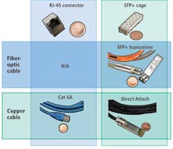
The least power-hungry option available to system integrators building 10 GigE systems is to use the SFP+ Direct Attach connectivity solution. The physical layer of a device using Direct Attach would consume around 1.5 W. On the other hand, the physical layer of an SFP+ transceiver/fiber-optic connectivity solution would consume around 2.4 W, while the physical layer of a Cat 6A copper-based cable solution would consume around 3.5 W. It should be noted that power consumption over Cat 6A cables should be expected to decrease further in the upcoming years as the telecommunications industry continues to execute on making 10 GigE over Cat 6A cable a mainstream solution. Power consumption over such a physical layer went from 6 to 3.5 W over the last 18 months alone.
Aggregation and objectives achieved
Just as 10 GigE was formally introduced by the GigE Vision standard, so too was the concept of link aggregation. Its adoption means that the interoperability between products that make use of the technique can be guaranteed.
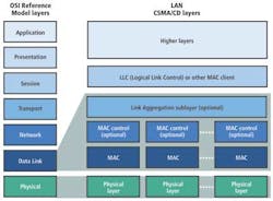
Version 2.0 of the GigE Vision specification defines how devices should operate in Link Aggregation Mode based on the IEEE 802.1AX Link Aggregation specification (see Fig. 2). The link aggregation control protocol sends frames down all the links that are part of the aggregation group. If a partner on the end of the link has the protocol enabled, the two units will be able to exchange data between themselves over multiple links combined into a single logical link. Because the link aggregation occurs at the Data Link layer, its operation is completely transparent to the GigE Vision Streaming Protocol (GVSP), which operates at the session layer of the OSI Network Reference Model.
However, there are some challenges when deploying a link aggregation scheme over a network because the IEEE specification does not clearly define how load balancing at a network switch should occur. This may then act as a bottleneck in the system, with the result that system integrators may not get their hoped-for system throughput.
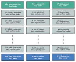
A second objective of the GigE Vision technical committee was to allow each of the packets sent over the network to contain more data through the formal adoption of the JPEG 2000, H.264, and JPEG compression techniques. This move would also increase the throughput of vision-based systems.
In order to ensure interoperability, the technical committee defined a method whereby data encapsulated by any one of the three compression schemes would be identified by a unique data leader, data trailer, and the compressed data contained within a number of data payload packets (see Fig. 3).
The third objective was to reduce thetransmission overhead of the GSVP for applications such as those that employ linescan cameras that output small images—at high frame rates—across the network.
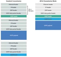
Traditionally, sending any video data over a GigE Vision video network involves some overhead because the packet not only includes image data but Ethernet, IP, UDP, and GVSP headers for each of the three elements of a GigE Vision block that encapsulates an image. To reduce this overhead, an All-in Transmission Mode is defined in the GigE Vision 2.0 standard that enables all elements of a GigE Vision block to be encapsulated within a single Ethernet packet (see Fig. 4). This transmission mode is advantageous and recommended for use only when it is possible to fit the image in a single Ethernet packet.
The fourth goal of the committee was to improve the time synchronization and also low-jitter network triggering of GigE Vision systems. This was achieved through the adoption of the Precision Time Protocol (PTP) described in IEEE 1588—a standard that allows distributed clocks to be synchronized over Ethernet networks with an accuracy of less than 1 µs.
Using IEEE 1588, a so-called "best master clock algorithm" builds a master-slave clock hierarchy for the system and selects what is known as the "grandmaster" clock for the system, after which each slave then synchronizes to its master. With all elements of the system now synchronized to the same clock, system developers can more easily build systems that perform operations such as triggering multiple cameras at the same time.
To improve the control of video data that flow around the network, the GigE Vision specification has also leveraged the flow control mechanism contained in another IEEE specification—this time, the IEEE 802.3 PAUSE frame mechanism. This mechanism enables receivers to provide an indication to transmitters that they are being overwhelmed with data. A receiver sends a PAUSE frame packet over the network, providing backpressure information to transmitters. The packet, which includes code to identify that it is a PAUSE frame, also contains the period of time for which the transmitter should stop sending data.
Featuring flexibility
Aside from these five key embellishments, other notable features have also been added to Version 2.0 of the specification. These include:
- 1) Support for interlaced video
- 2) Improved support of multitap sensors
- 3) Formal support of other standard enumeration protocols
- 4) Extended sequence identifiers
- 5) Pixel format naming convention
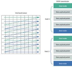
In transmitters that make use of interlaced scanning, the image is divided into two fields—odd and even—that are read out successively. In order to reduce the latency associated to the transmission of deinterlaced video over a network, GigE Vision 2.0 formally defines how interlaced video can be transmitted over GigE Vision. Although possible before, GigE Vision 2.0 allows interoperability across vendors. It does this by defining that interlaced video can be carried over GigE Vision by sending each field in its own GigE Vision block (see Fig. 5).
In many applications, the throughput of an inspection system is directly linked to the acquisition speed of a sensor. Multitap CCD sensors offer speed advantages compared to standard single-tap sensors because image data can be read out of the sensor in parallel via multiple taps. In the GigE Vision 2.0 specification, a method has now been provided to more efficiently output the data from multitap sensors.
The challenge faced by the engineers who developed the GigE Vision 2.0 specification was to provide a way to efficiently output the data from multiple taps while maintaining the ordering of the sequence identifiers found in the GVSP packets, which are used to determine if a packet went missing.
This was achieved by enabling a transmitter to define a number of horizontal zones from which data can be output simultaneously. In this mode, GVSP packets include an offset that identifies the starting position—in the image—of the data transmitted. This decreases the latency associated with the transmission multitap sensor by allowing image data coming from different zones to be output simultaneously, while maintaining the ordering of the sequence identifiers used for ensuring data delivery in GVSP. Data from multiple vertical taps no longer needs to be raster-scan ordered by the transmitter before transmission on the network.
Wishing to broaden the GigE Vision strict polling discovery process further, Version 2.0 of the specification now supports multicast DNS (mDNS) and DNS Service Discovery (DNS-SD). These protocols, which are widely deployed standard enumeration protocols, support device self-announcement, which was not supported by the GigE Vision device discovery method.
GigE Vision 2.0 also extends the block and packet sequence identification numbers that were defined in Version 1.2 of the specification. While Version 1.2 defined a 16-bit-wide block ID and a 24-bit-wide packet ID, the block ID has now been extended to a 64-bit width to facilitate the design of receivers, while the packet ID has been extended to 32 bits to make provisions for very high-resolution image sensors. Although the extension of the block and packet sequence numbers will offer advantages to developers, the GigE Vision 2.0 standard will only optionally support the standard ID mode. As a result, some hardware may not be supported by the existing software installed in current systems.
Last, a new pixel-format naming convention has been defined in a standalone document that will provide guidelines for developers of machine-vision standards to follow when defining the various pixel formats supported by a standard.
Version 2.0 of the GigE Vision specification was approved by the GigE Vision technical committee in November 2011 and was officially released by the AIA in January 2012.