Smart Camera Checks Electrical Tape
Hans Hansen
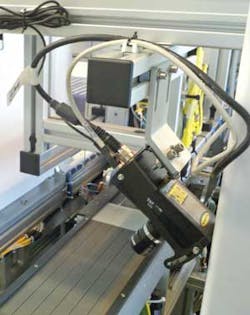
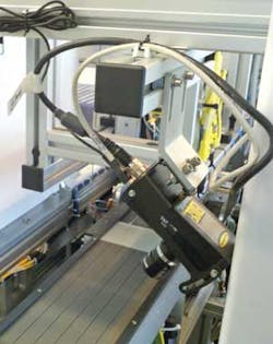
Emerging technologies often create novel design challenges, requiring designers to measure new materials under extraordinary situations. Insolar panel manufacturing, for example, various electrical components are first placed onto 0.3-mm-thick, translucent plastic electrical tape. To ensure correct 2-m lengths of tape are produced, the tape must be measured as it is drawn from a large roll. Owens Design has developed an automatic measurement system, based on a smart camera, that can ensure the tape is measured to an accuracy of 0.3 mm (see Fig. 1).
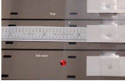
During processing, the tape is first drawn from a large roll onto an anodized aluminum vacuum table by a puller that attaches to the tape using vacuum cups. After various electrical parts are placed on the tape, it is cut to length. Then, the puller draws the cut strip of tape further, until a reflective sensor detects the leading edge of the strip and halts the puller (see Fig. 2). During the final approach to the sensor, the puller slows significantly to improve the repeatability of the pull to approximately 0.1 mm.
Smart system design
A camera locates the trailing edge of the tape to begin the measurement task. Since the tape and the vacuum table reflect light differently, it was possible—using the proper illumination—to create enough contrast between them to accurately measure the tape's length. A 1600 × 1200-pixel Presence Plus Edge smart camera fromBanner Engineering with a 25-mm lens was programmed so the edge-detection tool embedded in the camera could image both the strip end and a fiducial mark in the table. Since a relative—as opposed to an absolute—measurement can then be made, this approach compensates for any camera motion, making the system more accurate.
One of the biggest problems with accurately measuring the tape is obtaining high-contrast images so the edge-detection tool can consistently differentiate the edge of the transparent tape and the vacuum table surface. Initially, the camera was placed to capture vertical images from the end of the tape. Direct red lighting from an LED illuminator placed around the camera lens was used to illuminate the tape and table surface. Although this worked well initially, it started to fail when other types of tape materials were introduced by the customer due to differences in surface reflectivity.
To solve this problem, the camera was oriented so it viewed the tape at approximately 45°. A white area-array LED illuminator from Banner Engineering was then placed at a similar angle opposite the camera andpolarizing filters were placed on the camera and the illuminator. Using polarizers to enhance images of the translucent film to refract light in polarized waves produced a saturated area on the tape and a very dark area on the platen, resulting in good contrast images of both the tape end and the fiducial mark in the platen.
Edge detection
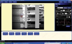
Triggered by aprogrammable logic controller (PLC), the camera images the tape and platen and embedded edge tools are first used to find both the fiducial and tape edge positions. After pixel edges are determined, an averaging tool in the camera is used to determine the best edge for the fiducial and tape. The difference between these two measurements is then calculated using the camera's Math tool and the result returned (in pixels) to a PLC register via Ethernet/IP. The data are then compared to a known good value to ensure the tape is within tolerance.
Figure 3 shows the edge profile of the tape. Above this profile are controls for setting the threshold used for image segmentation and other parameters. Jobs can be stored and retrieved, either via the camera memory or to an attached PC or laptop via Ethernet. During runtime, it is not necessary to connect a computer to the camera because the programming is stored in the camera. If any changes are required, the camera can be reprogrammed using an Ethernet-based laptop.
By first calibrating the system with a known good tape length, camera data in pixels can be converted in the system's PLC and shown in millimeters on the display. This known good value is also used to compare the recorded tape length with the camera's measurement and any offset programmed with user-selectable limits to indicate when a tape exceeds the correct length tolerance.
Reliability and repeatability
To ensure the system performed as expected, the reliability of its edge-finding capability needed to be determined. A number of measurements of the edge-location position were performed using the same piece of tape.
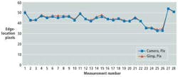
Digitized images of the edge location recorded by the camera were then stored off-line and, using the GNU Image Manipulation Program (GIMP), the edge locations were determined manually. These were compared with the results automatically generated by the system's smart camera (see Fig. 4). As can be seen, over a series of 28 different tests, the measurements obtained by the system (Camera, Pix) were consistent with those made manually (Gimp, Pix).
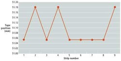
Similarly, it was also necessary to determine the repeatability of the tape puller since if the puller did not stop at the same place during every pull, the tape position would vary. A rule was placed arbitrarily on the aluminum vacuum table and the position of the tape at the end of each pull was then manually measured (see Fig. 5). Taking nine different measurements of the same tape, it can be seen that the puller repeatability was within 0.13 mm, well within the tolerance limits required.
Hans Hansen is senior systems design engineer at Owens Design (Fremont, CA, USA).
Company Info
Banner Engineering
Minneapolis, MN, USA
