3-D IMAGING: Digitizer captures 3-D images at fast data rates
Many different techniques currently exist to digitize three-dimensional objects, each of which has its own advantages. One common method uses a structured laser light that is projected across the field of view of the part to be imaged.
By capturing an image of the reflected laser light as the part or the camera/laser combination moves across the field of view of the object, a 3-D profile of the part can be captured -- albeit subject to laser safety issues and precision limits due to laser speckle noise and conveyor vibrations. To perform 3-D imaging of an entire area at once, techniques such as striped pattern projection can be used (see http://bit.ly/7n5Ein for additional information).

In this method, a number of striped phase-shifted patterns are sequentially projected across the object to be imaged. Phase-shifted images reflected from the object are then captured by a camera; 3-D coordinates are calculated based on the difference between the measured phase and the phase value from a calibrated reference plane.
Striped phase techniques have been used by companies such as 4DDynamics in developing a range of 3-D image digitizers that employ off-the-shelf digital light projectors and cameras (see "Off-the-shelf cameras and projectors team up for 3-D scanning," Vision Systems Design, February 2010). To achieve high accuracy, these systems typically require many stripe patterns to be sequentially shined on a stationary object. Alternatively, faster systems aimed at imaging objects in motion must use fewer patterns and thus have lower accuracy.
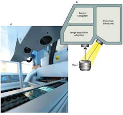
For machine-vision applications where accurate measurements must be made on objects traveling on conveyor belts, engineers at Numetrix Technologies realized that a custom approach would be required. The company's NX3D series of scanners employs a combination of split-spectrum light projection, dual-CCD camera technology, and the creative use of particle image velocimetry (PIV) triggering, which together capture enough image data to create precise 3-D models in 50 µsec. Objects can be imaged across a 4.7 × 3.5-in. field of view as they move at speeds up to 2.2 m/sec.
The reflected light from the object is captured in the NX3D's image-acquisition subsystem by two 1k × 768-pixel AD-081GE dual-CCD prism-based cameras from JAI. Within each camera, an embedded neutral beamsplitter splits the optical path, enabling a unique three-shot PIV trigger mode to be utilized. This mode allows users to shift the timing of the AD-081GE's two CCDs such that three closely spaced exposures can be captured instead of the two closely spaced exposures possible in a single CCD PIV camera.
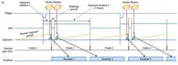
In a typical PIV mode, a trigger signal causes two strobe pulses immediately before and after the CCD's transfer gate (see Fig. 2a). This produces two exposures that are separated by only a short blanking period, although they still require two full frame periods for both exposures to be read out (33 msec for a 30-frames/sec camera). In a dual-CCD camera, offsetting the timing of the two CCDs enables an additional strobe pulse to produce a third exposure on CCD #2 between the two exposures that are captured on the first CCD (se Fig. 2b). A technical data sheet that fully describes this is available at http://bit.ly/KwkDrY.
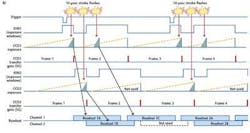
The NX3D digitizer uses each of the dual-CCD cameras in PIV mode such that a single trigger from the conveyor causes a total of six exposures to be accomplished in a period of 50 µsec and then read out over a two-frame period.
After all six images are captured by the system, a 3-D image can be computed, enabling the NX3D to model a 1 × 0.75-in. field of view at a depth resolution of 5 µm. Thanks to the acquisition time of 50 µsec, this accuracy can be obtained even on moving or vibrating objects.