Working with Lenses Beyond the Visible
Lucas Willis
With the availability of high-resolution indium gallium arsenide (InGaAs)shortwave-infrared (SWIR) sensors, infrared imaging is now practical in commercial and industrial inspection and imaging applications. As the number of SWIR imaging applications has increased, so has the need for affordable off-the-shelf SWIR imaging lenses. While much of the conventional wisdom regarding lens performance criteria in visible imaging translates well to SWIR, SWIR is not without its own unique set of challenges.
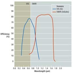
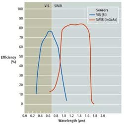
Infrared wavelengths exist in the part of the electromagnetic spectrum that extends from approximately 700 nm. The IR portion of the spectrum can be divided into sections generally referred to as near (NIR)/shortwave, midwave (MWIR), and longwave (LWIR). While no exact definitions exist, the 700-to-1800-nm SWIR wavelength corresponds approximately to the standard InGaAs sensor response curve (see Fig. 1). While there is considerable overlap between this definition and what is commonly referred to as near-infrared, NIR optics and sensors are usually restricted to wavelengths less than 1000 nm due to the sensitivity cutoff wavelength of standard silicon (Si) imagers.
In the past, IR imaging required large, expensive, mechanically/thermoelectrically refrigerated sensors with low resolution and slow frame rates. This made the technology impractical for many applications. Fortunately, advances in InGaAs technology have allowed compact cameras to be developed that do not require expensive cooling equipment.
Unlike Si sensors, InGaAs sensors require photodetector-basedfocal plane array (FPA) architectures that use an array of multiplexed photodetectors. Fabricating these arrays typically results in sensors with pixel pitches as small as 12.5 µm. Unfortunately, InGaAs fabrication methods and imperfections in the readout circuitry lead to high pixel-to-pixel photoresponse nonuniformity (PRNU). Although this can be compensated electronically, PRNU leads to a lower effective output image quality and signal-to-noise ratio (SNR), requiring high-contrast lenses to ensure that small image details are not buried by local signal variations.
Resolution and contrast
Resolution and contrast quantify the ability of an imaging system to reproduce details of an object. As with imaging lenses used in the visible spectrum, SWIR lens resolution can be described by the units of line pairs per millimeter (lp/mm) or alternating pairs of dark and light lines at a fixed spatial frequency. Spatial frequency is used interchangeably with "defect size" in imaging inspection applications, as a pair of pixels (one "on" and one "off") is needed to resolve an object. For a known defect or pixel size, this spatial frequency is calculated as
| Spatial frequency (lp/mm) = 1/(2 × Defect or Pixel size) in mm |
Optics manufacturers generally quote lens resolution in terms of image-space spatial frequency, which can be scaled to object resolution:
| Lens magnification:m = Sensor width/Object width |
| Object space resolution = Image space resolution ×m |
Image contrast is given as a percentage, most commonly defined as
| Contrast = (Imax – Imin)/(Imax + Imin) |
whereImax is the pixel intensity of the bright line and Imin is the intensity of the dark line.
The resolving ability of a lens and the effectiveness of machine-vision software mainly depend on having high enough contrast. Lower image contrast effectively provides a lower SNR. When the contrast is low enough, temporal and shot noise can make features indistinguishable.
Lenses effectively act as low-pass filters, producing images with successively decreasing contrast for components of increasing spatial frequency. This filtering can be described in the frequency domain with a transfer function, the contrast component of which is called themodulation transfer function (MTF.)
Modulation transfer function
Modulation transfer function is a very powerful way of describing lens performance and determines the expected image resolution and contrast for an arbitrary object. MTFs are normalized to 100% contrast at a spatial frequency of 0 lp/mm and decrease to a cutoff point where contrast is no longer reproduced. It is this decreasing contrast reproduction with frequency that leads to edges and transitions on the object being softened in the image. In lenses that are not corrected for aberrations to the point of having their performance be limited only by the physical effects of diffraction (which is usually the case), the cutoff frequency and the shape of the MTF curve form an effective measure of lens performance.
Because light diffracts as it passes through an aperture, even a lens that is fully corrected for aberrations cannot reproduce a perfectly sharp point at its image plane. Due to the nature of diffraction, the minimum spot size produced by a lens in the image plane is a function of both its aperture size (f/#) and wavelength (λ). For diffraction-limited systems with circular apertures, the spot that is produced is described by an Airy function, which is a circular peak containing roughly 84% of the spot's energy surrounded by diminishing annular rings. The diameter of this inner disk is often used as a figure of merit for the resolution of a lens and is given by
Airy disk diameter = 2.44 (λ ×f/#) where λ is the wavelength in mm
When the Airy disk diameter matches or exceeds the pixel size, the resulting image resolution is limited by the lens and not the sensor. This diffraction-limited spot size is directly proportional to both the wavelength and the lens aperture stop size. Thus, there is a spatial frequency at which the lens can no longer reproduce any contrast. The point at which the MTF curve tends to zero, is called the diffraction limit. The monochromatic diffraction limit in lp/mm is given by
| Diffraction limit = 1/ (λ ×f/#Eff) |
wheref/#Eff is the effective aperture, which is scaled by the lens magnification (m) according to
| f/#Eff = (1 + m) × f/# |
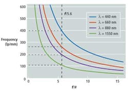
At infinite conjugate,m = 0 and thus f/#Eff = f/#. The aperture stop that is marked on the side of a lens indicates the effective aperture used for diffraction-limit calculations only at infinite conjugates. The effective aperture number needs to be calculated for all other lens magnifications. Figure 2 shows a plot of the diffraction limit as a function of effective aperture for four wavelengths from 440 to 1550 nm -- the significance of 1550 nm being a common laser wavelength for SWIR illumination.
While these numbers apply to perfectly focused, diffraction-limited lenses without aberrations, the curves have real-world applications. They represent the absolute best obtainable performance, in that each aberration (e.g., spherical aberration, chromatic focal shift, and defocus) decreases the contrast at a given spatial frequency.
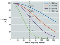
Figure 3 demonstrates theoretical monochromatic diffraction-limited MTF curves for four wavelengths atf/5.6, corresponding to the aperture indicated by the dashed vertical line in the plot of cutoff frequency (Fig. 2) with zero defocus. The cutoff frequency is the point at which the MTF curve intercepts the x-axis and contrast falls to 0%. As the wavelength increases, contrast decreases. For example, at 60 lp/mm, the maximum obtainable contrast is nearly 90% at 440 nm, falling to about 76% at 880 nm, and plummeting to 22% at 1550 nm.
Thus, the longer wavelengths of the SWIR band limit the contrast and resolution that is physically possible due to the wavelength-dependence of the diffraction limit. Although the effect is counteracted to some extent by the large pixels in present-day InGaAs SWIR FPAs, this becomes more important as pixel pitches decrease. Since maximizing contrast is critical for achieving high image quality, the already low diffraction limit necessitates careful lens design to minimize performance-decreasing aberrations.
Chromatic aberrations
Chromatic aberrations are extremely important in SWIR lens considerations largely due to the relatively large size of the waveband -- approximately 1000 nm as opposed to 400 nm for the visible band. In a single lens, a chromatic focal shift occurs; that is, the position of the focus point changes with wavelength. This aberration also exists in multielement lens assemblies but can be minimized with careful design.
When imaging a scene that is illuminated with multiple wavelengths (as is generally the case), each wavelength will tend to focus at a different location, so a compromise is made in focusing the lens to minimize the overall spot size. In poorly corrected lenses this compromise can result in a resolution many times lower than the diffraction limit because the image is essentially out of focus across much of the spectrum.
The standard method of correcting this wavelength-dependent focal shift relies on constructing pairs of lenses with low- and high-dispersion glasses to counterbalance chromatic focal shifts. The glasses are known as crowns and flints, respectively. Unfortunately, this method does not translate directly to the SWIR band. At those wavelengths there are no longer as many glass options to choose from to create this balance. Most glasses essentially begin to behave like low-dispersion crowns, leaving very few true flints from which to choose. This creates the design challenge of selecting suitable glasses to act as flints in the SWIR waveband to correct for color and decrease chromatic effects. This can lead to increased blur and lower resolution, while compensating for these glass effects on other lens aberrations also becomes difficult.
Lens choices
Using lenses designed for the visible spectrum but that are SWIR-coated optical glass is a common approach to creating an affordable, commercial off-the-shelf lens with relatively high transmission in the SWIR band. However, the standard optical glasses used are better suited for visible spectrum applications. As outlined in the chromatic aberration discussion previously, some very drastic effects to the lens resolution can be realized when using this option.
Until recently, building high-performance SWIR lenses typically required custom application-specific designs. Such high-performance lenses generally incorporate crystalline and diffractive elements to achieve wideband aberration correction. Processing these somewhat exotic materials increases manufacturing costs and can require large minimum-order quantities to justify their initial engineering expense.
An alternative approach is to deploy glass lenses designed specifically for use in the SWIR band. These offer a considerable performance increase over SWIR-coated visible lenses at a slight increase in cost. With carefully selected optical glasses and wideband coatings, SWIR lenses are well corrected and can be manufactured more easily than lenses with crystalline and diffractive elements. However, this process does not just involve repositioning optical element locations of visible lens designs and changing the antireflective coating—a ground-up design effort is required.
Lucas Willis is a machine vision solutions engineer at Edmund Optics (Barrington, NJ, USA; www.edmundoptics.com).
SWIR imaging enables fine art analysis
One of the more interesting applications benefiting from shortwave-infrared (SWIR) imaging is fine art analysis, enabling art historians and curators to look beneath paintings to reveal details beyond what is seen with visible inspection. SWIR imaging of art can also provide high enough resolution to differentiate multiple layers of paint, and SWIR imaging systems are being used to validate authenticity and evaluate paintings that have been restored.

The Last Judgment by Jan Provost was imaged in the SWIR waveband using aUTC Aerospace Systems (www.sensorsinc.com) GA1280J-15 high-resolution SWIR camera at the Detroit Institute of Arts (www.dia.org), detailing the artist's original intention by carefully examining the underdrawing that lies beneath the paint film. Edmund Optics' TECHSPEC SWIR fixed focal-length imaging lenses -- designed, coated and tested for the SWIR wavelengths 0.9-1.7 μm and used with the camera -- have the resolution and contrast to distinguish fine pencil marks behind the paint, offering insight into the design and revision process of the artist to understand the original intention of historic masterpieces.
One can see 10 trumpets underneath the archangel versus the 5 trumpets that were painted. The placement of the painted trumpets appears to have necessitated a repositioning of the sailing vessel. The toes on top of the globe were also not painted in the same location as the original underdrawing.