By Andrew Wilson, Editor
Postal service, business, and private-carrier mailrooms process thousands of letters and packages every working day. Any one piece of mail or box could harbor an explosive device. To help stop this dangerous menace, mail-service companies are seeking to implement x-ray-type detection systems that can accurately distinguish between an explosive device or weapon and a nonthreatening object such as a pen or cell phone. If the x-ray screener is easy to use and can rapidly process all scanned items, then mail delays are reduced and security is ensured. By user definition, the detection system must be durable, reliable, and accurate, with no margin for error.
Cabinet-based x-ray and conveyor systems are the most common types of screeners used in mailrooms. While cabinet-based machines are suitable for screening letters, mail trays, and packages, conveyor systems are found in organizations with large mailing operations. Both systems enable operators to view the contents of packages on a screen and, in some cases, highlight suspicious areas.
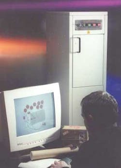
For example, Scanna MSC Ltd. (London, UK) is addressing these needs with its Scanmax 25, which can screen packages as large as 20 × 15.7 in. Designed to scan bundles of letters, courier deliveries, parcels, and handbags, freestanding and wheeled systems are available in both monochrome and color versions (see Fig. 1). They are installed in mailrooms of companies, government agencies, and embassies worldwide.
null
The Scanmax 25 uses a source to transmit x-rays through its viewing chamber. The number of x-rays that penetrate a mailing package placed within this chamber and are not absorbed by the package depends on the density and the thickness of the object. X-rays not absorbed by the object are converted to visible radiation on a fluorescent screen.
Depending on the quantity of x-rays hitting the screen, shadow images are produced. The system then displays these images of the object based on its density. In this way, the mail detection system can differentiate between cardboard boxes and fabrics, which absorb few x-rays, aluminum and porcelain, which absorb a larger number of x-rays, and steel and lead, which absorb all the x-rays.
System design
Scanna MSC designed and built the mail detection system. According to Sam Mazzotta, scanner operations director, the Scanmax range of postal x-ray screening systems incorporates both custom and off-the-shelf imaging components.
null
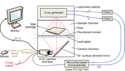
Positioned near the top of a lead-lined cabinet, an x-ray generator emits the x-rays that pass through the package to be examined (see Fig. 2). This x-ray generator and other parts of the imaging system are controlled by a stand-alone computer board that uses the PIC16C74A microcontroller from Microchip (San Jose, CA). The microcontroller is programmed to control both the x-ray generator and the trigger functions of a VC21 camera from Vision Components (Ettlingen, Germany) that captures the x-ray images.
During operation, two Triacs are triggered by the microcontroller to adjust the high-tension circuit within the x-ray head for specific x-ray densities. Gated pulses from the microcontroller board set the voltage and current values at the x-ray head. When these Triacs are energized, generated x-ray energy passes through the mail package placed in the chamber and onto a fluorescent screen.
Fluorescent, 8-bit gray-scale images are then imaged by the VC21 camera; this DSP-based camera provides 782 × 585-pixel resolution at 25 frames/s, an on-board 160-MIPS ADSP2181 processor, 2 Mbytes of DRAM, and an SVGA video output with 1-bit color overlay.
Cross compiling
Using a Scanna proprietary program, the camera is programmed in C using a cross-compiler running on a standard PC. Source code was written using Microsoft Visual Studio in conjunction with a development suite from Vision Components. This program also incorporates an ADSP2181 cross compiler and linker from Analog Devices (Norwood, MA) and camera support libraries from Vision Components.
The compiled program is downloaded to the camera over a serial (RS-232) connection and stored in the camera's Flash file system. "The program was debugged using a combination of diagnostic reports over the serial link and on-screen displays incorporated into the program," says Mazzotta. The VC-21 camera was selected because it supports the long exposures required to capture images from the dimly glowing fluorescent screen. In addition, technical support provided by Image Management Technologies (Petersfield, Hampshire, UK) helped to develop the vision system within months at low cost.
At system powerup, the camera displays the current image zoom level and selected color map on the monitor screen. Then it captures an image of the object placed in the viewing chamber, and this image is displayed until the user switches off the x-ray system or takes a new x-ray exposure.
null
The user can choose one of four zoom levels and six color maps. These maps consist of a black-and-white image, brightness-intensified image, negative image, and three pseudocolor maps (see Fig. 3).
"Depending on the programming, a particular level of light will give a different color result for the object being viewed," says Mazzotta. Color maps are defined according to the density of the material being x-rayed. For medium density, Scanna uses orange and green. If a letter bomb is placed in the machine, for example, the explosive material will be highlighted in red. "The color map feature benefits the user by drawing attention to suspect areas," adds Mazzotta.
Captured images from the camera are output in real time to a standard SVGA monitor. At the same time, an external mouse control linked to the camera enables the operator to make on-screen image enhancements from the desktop computer.
The images displayed by the VC21 camera offer users a more-accurate approach to detecting contraband sent through the mail than those produced by a conventional camera. The VC21 incorporates an SVGA graphics display that supports the false-color maps. Its serial port provides the interface to the tracker ball. The on-board DSP enhances the images for display.
