PCMC (Green Bay, WI, USA; www.pcmc.com), is a leader in tissue converting, packaging, flexographic and digital printing, bag converting and nonwovens technology. Its digital printing offering needed a vision system to verify that the printheads on its digital press were aligned. The company considered common line scan cameras, but the distortion at the ends of the field of view along with the added working distance were two challenges. The application is on a two-stage industrial inkjet print engine (Figure 1) that prints on a web running at over 450 feet per minute (fpm). One stage prints the front (recto) and the other the back (verso) of the web.
Each engine stage has four printbars—one for each color: black, cyan, magenta, and yellow (KCMY)—and each printbar has two printheads to cover this application’s web width. The eight printheads on each stage must be aligned for the dots in the four color planes to be perfectly positioned to reproduce the gamut of visible colors. If the four colors are not aligned, color reproduction suffers because the KCMY dots are not positioned correctly relative to each other, distorting the intended color. Also, unintended white outlines or color “halos” appear at the edges of graphic objects. The vision system is used to automate the alignment process and prevent these errors.
Manual versus automatic alignment
A press operator typically realigns the printheads after changing substrates, after replacing printheads, or after any mechanical work on the printbars. According to Fabio Girolami, Systems Engineering Manager at PCMC, who handled the vision system integration, the manual process for aligning the printheads included the following steps.
The operator cued up the alignment chart to the print engine, ran the web at approximately 150 fpm, and printed about 10 copies of the alignment chart. The operator waited for the printed charts to reach the end of the press, stopped the web, and collected the alignment charts at the end of the press.
“Typically the printed web is delivered onto a roll, so the web had to be cut and the roll partially unwound to get at the charts,” says Girolami. The operator cut out one front and one back chart and placed each one on an 11 × 17 in. flatbed scanner and scanned to a TIFF file at 300 dpi. The operator then pointed the print engine’s calibration function to the scanned files to perform image analysis on the alignment charts, calculate the deviations, and apply the corrections.
")
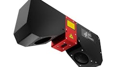
According to Girolami, the new process provides a much quicker and less wasteful (time and material) method for aligning the four color printheads. Employing the “automatic” process, the operator cues up the alignment chart to the print engine, runs the web at approximately 150 fpm, prints about 10 copies of the alignment chart, and the web can immediately be stopped. A contact image sensor (CIS) (Figure 2) and frame grabber capture the front and back alignment charts concurrently and write the TIFF files to the print engine’s control PC. The print engine’s calibration function performs image analysis on the TIFF files, calculates the deviations, and applies the corrections. The calibration function reports either a successful result or a fault.
“The operator needs to deal with the fault,” says Girolami. “For example, if a printhead was not properly locked into position, the image analysis would determine a larger than normal alignment error and fail to apply the corrections. The operator would have to troubleshoot the problem with the identified printhead, fix it, and then redo the alignment process.”
CIS camera and frame grabber at the heart of the system
The vision system comprises two camera setups installed on the digital press—one for each stage (front and back). The vision system’s principal components include a contact image sensor, a frame grabber, an encoder, an encoder splitter, and a control PC.
")
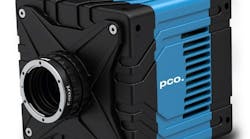
Mitsubishi Electric (Cypress, CA, USA; www.us.mitsubishielectric.com) provided the system’s CIS, a KD6R587CXS CIS Line Scan Bar (Figure 3) featuring a 587 mm scan width, 600 pixels per inch for a total of 13,824 pixels, and a CoaXPress interface. According to Lou Fetch, Business Development Manager, CIS and MICMO Products at Mitsubishi Electric, “The 1:1 imaging of the CIS line scan camera and low profile makes this an ideal application for our KD camera.”
Illumination for the camera is highly intensive and homogeneous LED lighting integrated directly in the frame of the sensor housing, so the illumination is always optimally aligned to the sensor. Calibration and alignment of external light sources is unnecessary.
")
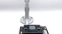
Euresys (Angleur, Belgium; www.euresys.com) supplied its Coaxlink Quad G3 frame grabber (Figure 4) along with its eGrabber software library, utilities, and drivers that are used by the application software written by Memjet (San Diego, CA, USA; www.memjet.com). PCMC uses the software to analyze the color alignment of the multiple printheads to ensure best color and print quality quickly and with minimum waste.
Michael Cyros, Vice President, Sales and Support for the Americas at Euresys, says, “As is always the case, the frame grabber is usually the lowest cost item in the system built but acts as the nerve center for the entire application and therefore requires the most technical support. This was how we got to know Fabio and his team quite well at PCMC in Montreal, Canada, and also the reason we have really good working relationships with Mitsubishi Electric and Memjet.”
Euresys also supplied customized lengths and configurations for the necessary CoaXPress cables for controlling and obtaining images from the CIS imagers and system I/O. These cables interface the Coaxlink Quad G3 boards directly to the quadrature encoder on the press and provide other system timing signals where needed.
Cyros explains that the Coaxlink Quad G3 frame grabber provides several onboard features used by the Memjet software including real time gamma correction, color conversion, and an important flat field correction (FFC) that does a per pixel correction of each pixel coming from the Mitsubishi Electric CIS imager to adjust for any variability in the illumination cross-web to ensure even and consistent lighting.
“One of the key strengths of our Coaxlink series of CoaXPress frame grabbers/image capture cards is that we have a really flexible and programmable encoder interface to precisely control the exposure time and line frequency of the Mitsubishi Electric CIS imager as well as controlling the integrated LED lighting,” he adds.
Programmable I/O with fractional (non-integer) trigger scaling is a key component in a successful CIS implementation, according to Cyros. No matter what the web speed is, triggering the imager precisely to the down web motion is required to ensure that imaging is done at the exact dpi resolution required of the application.
"In a typical Memjet application, the imaging resolution is done at 300 dpi in both the cross web and the down web directions to for precise color-to-color registration of the printing system," Cyros says. "While the cross web resolution is fixed by the Mitsubishi Electric CIS imager, the down web resolution is variable as the printing system speeds up and slows down. The Coaxlink series of CoaXPress frame grabbers take the input from the web encoder and can scale the line trigger sent to the imager accordingly to ensure that the imager is always imaging precisely at 300 dpi down web, no matter what the speed of the web is.
"Encoder Products Company (EPC) (Sagle, ID, USA; www.encoder.com) provided the Model 260 Accu-Coder encoder and RX/TXD encoder splitter.
Finally, the system’s control PC is the 9021-PCMC-CVPC from Proactive Technologies (Carrollton, TX, USA; www.proactivetechnologies.com). It features a 4U industrial rackmount server chassis, an ASRock (Taipei City, Taiwan; www.asrock.com) Z590 Pro4 motherboard, and an Intel (Santa Clara, CA, USA; www.intel.com) Core i9-10850K processor.
Preliminary in-house testing showed that the whole system produces accurate alignment. At this time, there is only limited feedback from the operating site. More experience is expected in the coming months. Overall, Girolami is pleased with the system’s performance.
“Everything performed as expected. Great support from Euresys and Mitsubishi Electric on getting our first application built, configured, and started up.” Cyros adds, “Fabio is the guy who specified all components, coordinated their purchase, architected the changes to the PCMC press systems to accommodate the imaging, and put it all together. Fabio really played a key role in making this project a success!”