Eliminating blind spots in industrial machine vision
By Arnaud Destruels, European Visual Communication Product Manager, Sony Europe Ltd
Machine vision has played an unarguable role driving up the quality of in-line inspection systems. And not just a subset of processes, but for a near unending set.
Today, global shutter CMOS sensors can capture at exceptional resolutions and speeds - for example the Sony IMX-250, which is used in the Sony XCL-SG510 module to deliver 5.1 MPixel images at 154 fps - and integrate ever more advanced features, including the recent launch of polarized-light sensors for machine vision modules, which removes glare and highlights potential issues more easily. Similarly features such as wide dynamic range, area gain and defect correction are implemented on many modules.
Improvements in transmission standards, and the bandwidth they provide, enable ever more advanced features to be delivered to - from GigE’s use of the IEEE1588 precision time protocol for synchronizing the firing of modules, lighting, robotics etc.; to those that give extra information such as wide dynamic range.
And, of course, processing power has improved in line with Moore’s Law.
The blind spot
Most machine vision systems inspect a part’s surface only, with the component being held by a manipulator or mounted on a guidance system. This limits the analysis to only a particular segment of the 3D geometry or requires mechanical changes for each new batch, which must also be free of mixtures of different parts.
On display for the first time at the Vision Show 2018 will be a new prototype that claims to offer a new way of working. The Instituto Tecnológico de Informática (ITI) in Spain in conjunction with Sony are developing what they call “the industry’s most versatile machine vision inspection system”, Zero Gravity 3D.
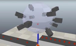
The system removes the blind spot by launching an object vertically into an imaging chamber to precisely capture it from multiple angles while in flight. This process means the geometry and entire surface of even highly complex components can be captured from 360o with no blind spots.
The technology has successfully completed proof of concept testing and the ITI and Sony will continue to collaborate and bring the system to market.
System setup
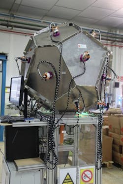
ITI’s prototype uses 16 Sony XCG-CG510C GigE modules - ITI is also able to scale the imaging chamber size, with the number of cameras changing as it scales. The 16 modules each output 5.1MPixel images at a frame rate of 23 fps.
The output of these cameras is then transmitted via the GigE standard and stitched together digitally, enabling an operator to digitally rotate an image and examine any potential flaws picked up by the system.
Objects enter the imaging chamber from a conveyor belt, which places the component into a polyhedral structure. This is connected to a linear motor which fires the object vertically. Once captured and in free-fall, the object is caught by the same linear actuator moving to match the object’s speed and prevent impact and off-loaded to a second conveyor belt, or tray.
With the object moving at a relatively high speed, synchronization is essential - with any mistimed firing resulting in a corrupted image. To achieve this, the modules utilize the IEE1588 precision timing protocol with firing timed to match the top of the object’s flight. Using IEEE1588 also allows the imaging chamber’s LED lighting to be synchronized with the module’s firing.
The XCG-CG510 is one of a small group of camera modules that allow IEEE1588 master functionality, enabling any module to be dynamically assigned as the master should a device fail - giving ITI the reliability it needs.
The proof of concept technology has been tested running at 50 parts per minute with a single linear actuator, or 80 parts per minute in a dual-actuator imaging change.
Applications
This process allows manufacturers to run multiple types of components for analysis in a single batch, and to easily switch components being captured without mechanical changes
Applications include three-dimensional surface reconstruction with textural analysis, as well as surface defect detection, be it a scratch, stain, crack, corrosion or geometric alteration.
Note: The system will be available for the first time to view at VISION 2018 in Stuttgart, Germany from November 6-8 on the ITI stand, Hall 1, Stand A74. Sony’s cameras will be available to view in Hall 1, Stand C37.

