3D imaging: 3D imaging enables high-speed bore inspection
New inline-inspection applications are being developed for industry thanks to advances in high-speed, low-coherence interferometry, a high-resolution three-dimensional (3D) imaging technology. Precision bore holes, for example, must adhere to strict geometric dimensioning and tolerancing (GD&T), including straightness, cylindricity, circularity, taper, distortion, runout, roughness characteristics, semi-transparent coating thickness, or defect characterization. Also, features on the insides of bores, such as threads, O-ring grooves, undercuts, chambers, and cross-holes, must often be characterized with high precision to ensure that components ultimately interlock, seal, fit, or otherwise function as intended.
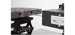
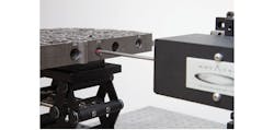
A 3D imaging system based on high-speed low-coherence interferometry is being used for the automated inspection of bore holes.
Understanding this, Novacam Technologies (Pointe-Claire, QC, Canada; www.novacam.com) has developed a system, dubbed BoreInspect, that provides fast, micron-precision, non-contact measurements of bore internal diameter (ID) surfaces.
Vuk Bartulovic, President of Novacam, says "By the time they come to us, many of our clients have spent a long time looking for a way to measure, in a non-contact manner, internal diameters of bores, cylinders, and other such hard-to-reach spaces. These bore diameters range from a few millimeters to as large as truck engine cylinder bores. Typically, they want to acquire full internal diameter dimensions, detect defects, and measure roughness. It is a revelation to them that an instrument exists that can provide all this functionality … and that micron-precision data on their bore ID can be acquired in a matter of seconds and in a non-contact manner."
The system automatically generates and presents the operator with a display of the four bores, along with an evaluation of crucial measurement criteria.
The system has been deployed for automated 3D metrology of valve-body assembly bores. Following a user-created inspection sequence, all four bores in the valve body are automatically scanned, and the resultant 3D surface point-cloud analyzed and displayed using PolyWorks from InnovMetric (Québec, QC, Canada; www.innovmetric.com), a third-party 3D data visualization and metrology software. According to user criteria, selected aspects of each bore are compared to actual measurement data and non-compliance visually highlighted.
Comprised of three main hardware components, BoreInspect includes a rotational scanner that spins a non-contact optical probe while a robot or motion stage advances it into the bore hole. The side-facing probe directs a low-coherence light beam at the surface and collects reflected light signals. The second main component, a profilometer, provides the light source to the rotational scanner via a fiber-optic cable and processes the optical signal received from the scanner. Finally, a PC provides the user interface for data acquisition control and data-analysis software. It also typically houses client-selected 3D- visualization and metrology software.
High-density point clouds generated from its scans enable rapid and detailed characterization of inner surfaces and features as well as defect detection. During operation, the scanner spins the probe at 1,800 rpm, acquiring 30,000 3D surface measurements per second. In just over 3 seconds, 100,000 surface measurements on the inside of the bore are collected, providing a high-fidelity 3D model of the bore ID.
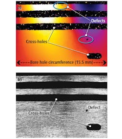
Along with a 3D point cloud, 3D height data (top), and a light intensity image (bottom), can be obtained and used for defect detection.
For the automated valve body bore metrology application, the rotational scanner enters each one of the four valve body bores in an automated sequence and the system automatically generates and presents the operator with a display of the four bores, along with an evaluation of crucial measurement criteria. A deviation map, highlighting the deviation of the measured bore dimensions from the CAD model, helps reveal micron-level surface defects.
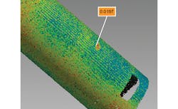
To help manufacturers gain insight into the process, BoreInspect can be configured to provide deviation maps highlighting the deviation of the measured bore dimensions from the CAD model, to reveal micron-level surface defects such as this 19.7-micrometer deep depression.
"Regardless of the bore diameter, the accuracy of the non-contact 3D measurements is the same," explains Bartulovic. "Defining scanning sequences is easy and each sequence may be saved for later recall and execution. While the user may manipulate and analyze the 3D point cloud data in an interactive manner, the BoreInspect system also generates automated reports."
The system is suitable for integration into automated continuous flow manufacturing, according to Vuk. "Its compact, modular, and rugged design facilitates integration, even in high-throughput industrial metrology applications that would have the scanner mounted on a stage suitable for the application, such as a robot arm, gantry, or motor-controlled stage, and the optical fiber connection to the system's interferometer can be hundreds of meters long."
Currently, Novacam's rotational scanners feature probes with diameters between 1 and 18 mm. Standard probes inspect bores with diameters ranging between 6 and 28 mm, however Novacam builds custom systems for bores with diameters less than 2 mm and from 30-222 mm.


