Embedded camera brings 3D mapping to boring machines
Mounting an embedded camera within the cutting head of a tunnel boring machine allows contractors to document rock face structures as boring progresses.
Robert Wenighofer
In the past, drilling and blasting methods were used to excavate tunnels, a process that was labor intensive and time consuming. Today, more efficient tunnel boring machines (TBMs) are used as an alternative, producing smooth tunnel walls while limiting any disturbances to the surrounding soil or rock. Although expensive, such TBMs have the advantage over drilling and blasting methods since, when tunnel lengths are long, they promise to be more efficient and can perform such tasks in a relatively short period of time.
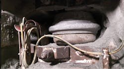
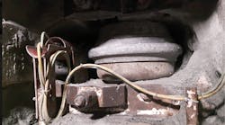
Figure 1: Multiple disc cutters are used in a tunnel boring machine to cut the rock-face. In a single disc housing, the disc cutter (middle right) shown in this front elevation, rotates as it cuts the rockface. By housing a GigE camera and control unit (shown in red) within this disc cutter (top, left), a circular 85° field of view (FOV) of the face can be imaged as the TBM rotates.
One of the advantages of drilling and blasting methods, however, is that open access is provided to the tunnel face, making it relatively simple to observe, analyze and record geological features. Such geological mapping is more difficult when using mechanized tunneling methods, since the cutting head obstructs the view of the tunnel face. To overcome this, the Institute for Subsurface Engineering at the Montanuniversität Leoben (Leoben, Austria; www.subsurface.at, www.unileoben.ac.at) has developed an embedded camera system to provide 3D reconstructions of the tunnel face. In operation, the system visualizes the spatial position of stratifications, the depth of any cavities and any discontinuities of the rock.
Developed in collaboration with Geodata Group (Leoben, Austria, www.geodata.at), the system comprises an off-the-shelf camera mounted in a ruggedized housing and a control unit mounted in the disc cutter housing of the TBM (Figure 1). In a single disc housing, the disc cutter (middle right), shown in front elevation, rotates as it cuts the rockface. Currently, the TBM is building the exploratory tunnel of the Brenner Base Tunnel, the world's longest tunnel now under construction. The camera system was deployed at Tulfes-Pfons section of the tunnel at Innsbruck, Western Austria by a joint venture between Strabag AG (Cologne, Germany; www.strabag.com) and Salini Impregilo S.p.A (Milan, Italy; www.salini-impregilo.com).
After cutting, it is necessary to visualize any new geological features that may be present. To do so, the boring machine is retracted and the material between the cutter head and face cleaned. A GigE camera (shown in red) and control unit housed within one of the disc cutters (top, left) then images a circular 85° field of view (FOV) of the face as the TBM is manually rotated away from the rockface.
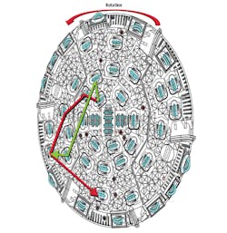
Figure 2: Cutter head of the TBM. To obtain a complete image of the rockface, the camera is placed at either four (shown in green) or five positions (shown in red) within disc housings of the cutting head while the camera controller is constantly mounted in a double disc cutter near the rotation axis of the TBM. This results in between either 700 or 1100 images being captured depending on whether four or five positions are employed.
To expand this coverage, the same camera system is then re-positioned in a different disc housing, and the TBM manually rotated again. This process is then repeated at four or five different disc housing positions approximately four or five times (Figure 2). While the TBM head rotation takes approximately 3 mins, it takes 10 to 15 mins to then reposition the camera system at each different disc housing location. To expedite this process, it would at first appear that several embedded cameras could be used. However, the massive 25-ton force that a single disc cutter exerts and the tons of excavation material produced would impede permanently mounting a camera system in the cutter head.
Camera and controller
To image the rockface as the TBM head is manually rotated, a Prosilica GT2000 GigE camera from Allied Vision (Stadtroda, Germany; www.alliedvision.com) with a 2/3in CMOS 2048 × 1088 sensor from ams Sensors Belgium (Antwerp, Belgium; www.cmosis.com) was fitted with a 5mm focal length C-Mount lens to provide the 85° FOV of the face. The camera system is housed in a ruggedized housing incorporating a white LED ring light developed by Geodata Group (Leoben, Austria; www.geodata.at). While the camera is operated in a continuous mode, capturing two frames per second, the white LED is strobed over a period of 4ms to ensure a visible light output of 10,000 Lumens so that no motion blur occurs as the camera system is rotated. This level of illumination is sufficient to illuminate break-outs in the rockface of more than 1.7 m depth as can be seen in Figure 4.
As images are captured by the GT2000 camera, they are transferred over its GigE interface to a fanless quad-core embedded PC from Vecow (New Taipei City, Taiwan; www.vecow.com) that acts as a camera control unit. Camera control software running on the PC, based on Allied Vision's Vimba SDK, triggers the camera at 2 fps which provides sufficient overlap between images to perform 3D reconstruction and a surplus of images. To ensure that the position of each image is known as the TBM head rotates, the camera control unit incorporates a uniaxial inclination sensor from Posital Fraba (Heerlen, The Netherlands; www.posital.com) mounted inside the camera controller and interfaced to the embedded PC over an RS-232 interface.
In this way, as each image is captured by the camera, it is assigned an angular value from the inclination sensor. This inclination angle and the known relative position of the disc housing is then used to determine the absolute position of the camera in the 3D coordinate system of the cutter head. Knowing this information, both two-dimensional and 3D photogrammetric data of the rockface can then be generated.
It is necessary to visualize the quality of the images of the tunnel face before the TBM is rotated to ensure that the image quality is acceptable and that the protective glass of the camera unit is not fogged up or soiled. Because of this, the camera controller is set to automatically initiate recording after the camera control unit has powered up. Then, by incorporating a wireless network card in the camera controller, stationary images can be analyzed remotely using any Android-powered handheld device such as a smartphone or a personal digital assistant (PDA).
Mapping the face
To obtain a complete image of the rockface, only the camera unit is placed at either four (shown in green) or five positions (shown in red) within the disc housings of the cutting head. This results in between either 700 or 1100 images being captured depending on whether four or five positions are employed. After each image is captured, it is stored along with is associated unique angular value from the inclination sensor. After these images are captured, the camera and camera controller are removed and the data transferred over a USB interface to an Intel i7-based desktop PC with a GTX970 PCI Express graphics card from NVIDIA (Santa Clara, CA, USA; www.nvidia.com).
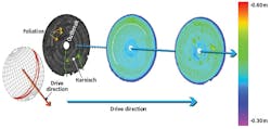
Figure 3: Using the 2D image sequences generated as tunneling progresses, geologists can characterize and measure such features as spatial discontinuities and visualize the tunnel face and the behavior of the excavation process as it continues
To generate 2D and 3D maps of the rockface and allow image measurements to be made, captured images are then processed using the Photoscan software package from Agisoft (St. Petersburg, Russia; www.agisoft.com). Using this software, the camera can be first calibrated before use to rectify any possible distortion from the camera's lens as well as computing the parameters of the camera matrix such as the focal length and projection center of the lens. This information along with each 2D image and camera position data from the inclination sensor is then processed by Photoscan in a process known as bundle block adjustment. In this process, a set of 2D images are taken from different viewpoints and the relative motion of the camera and its optical characteristics are used to generate an optimal 3D reconstruction of the scene.
Using the 2D image sequences generated as tunneling progresses, geologists can characterize and measure such features as spatial discontinuities and visualize the behavior of the excavation process (Figure 3). In this example, three images of the rock face are shown as tunneling progresses (from left to right). In the monochrome image on the left, there is a failure of the tunnel face which may be due to structural weakness in the rock. To further analyze this structural weakness geological features like schistosity can be displayed (graphic, far left) as a stereographic projection. This is accomplished using a software plug-in based on the .NET application programming interface (API) of AutoCAD software from Autodesk (San Rafael, CA, USA; www.autodesk.com).
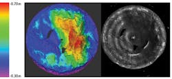
Figure 4: Color-coded elevation images that represent the distance between the cutting head and the tunnel face can also be used to detail the structure of the surface of the face. In this color-coded image of the rockface (left), a huge break-out can be clearly visualized.
Color-coded elevation images that represent the distance between the cutting head and the tunnel face can also be used to detail the structure of the surface of the face (Figure 4). In this color-coded image of the rockface (left), discontinuities can be clearly visualized. This is important since, when tunneling, the cutting disks will be subject to different forces at different points on the surface possibly requiring later repair or replacement to the cutting discs. For contractors to objectively document this is vital since any such possible repairs may be expensive and need to be passed on to their customers.
Field-tested in the construction of the Brenner Base Tunnel in the Austrian Alps, the camera system has been used for more than a year where it has proven to be an appropriate means of documenting and visualizing the rockface even in the harsh environments created by TBMs. Patent protection for the system is currently being sought in Middle-Europe.
Reference:
Wenighofer, R., Galler., R., Six, G., Chmelina, K.: Cameras for the digitized 3d geological documentation of the tunnel face from cutter heads of TBMs, Geomechanics and tunneling, 10 (2017) No. 6, 760-766
Robert Wenighofer, The Institute for Subsurface Engineering at the Montanuniversität Leoben(Leoben, Austria; www.subsurface.at)
Companies mentioned
Agisoft
St. Petersburg, Russia
www.agisoft.com
Allied Vision
Stadtroda, Germany
www.alliedvision.com
ams Sensors Belgium
Antwerp, Belgium
www.cmosis.com
Autodesk
San Rafael, CA, USA
www.autodesk.com
Geodata Group
Leoben, Austria
www.geodata.at
NVIDIA
Santa Clara, CA, USA
www.nvidia.com
Posital Fraba
Heerlen, The Netherlands
www.posital.com
Salini Impregilo S.p.A
Milan, Italy
www.salini-impregilo.com
Strabag AG
Cologne, Germany
www.strabag.com
The Institute for Subsurface Engineering at the Montanuniversität Leoben
Leoben, Austria
www.unileoben.ac.at
Vecow
New Taipei City, Taiwan
www.vecow.com